StudentShare
Contact Us
Sign In / Sign Up for FREE
Search
Go to advanced search...
Free

Design of the New Nose for Open-Wheel Climb Race Car - Lab Report Example

Cite this document
Summary
The paper "Design of the New Nose for Open-Wheel Climb Race Car" states that the most important function of the nose was to make the flow more smooth to pass through up to the front wing and under the tray. The nose cone does not produce downforce for the car but it generates the lift for the car…
Download full paper File format: .doc, available for editing
GRAB THE BEST PAPER92.7% of users find it useful
Design of the New Nose for Open-Wheel Climb Race Car
Read Text Preview

Extract of sample "Design of the New Nose for Open-Wheel Climb Race Car"

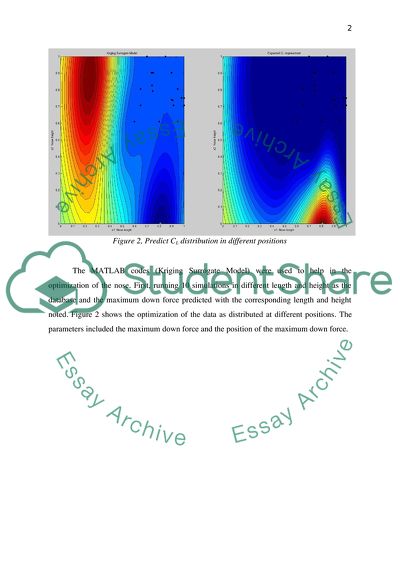
5. OPTIMIZATION (NOSE) 5 OPTIMIZATION OBJECTIVE (NOSE) By changing nose height and length to find the maximum down force 5.2 OPTIMIZATION TEST (NOSE) There are many parameters that are used to designs nose models. Previous test of the first design, found that any change in length and height of nose cone has a net result on the aerodynamics properties. The optimization test is aimed at finding the results of changing the height and length of nosecone on the aerodynamics effects. Specifically the effect on the drag and down force of the nose and other components was tested by optimization test. Figure 1 shows the tested parameters for the nosecone. After 1st design the nose length=600mm and height=102.8mm. The optimization test parameters length setting from 500mm to 700mm and height from 102.8mm to 142.8mm. Figure 1, Tested parameters in optimization (length and height) Figure 2, Predict CL distribution in different positions The MATLAB codes (Kriging Surrogate Model) were used to help in the optimization of the nose. First, running 10 simulations in different length and height as the database and the maximum down force predicted with the corresponding length and height noted. Figure 2 shows the optimization of the data as distributed at different positions. The parameters included the maximum down force and the position of the maximum down force. 5.3 OPTIMIZATION RESULTS AND ANALYSIS (NOSE) no Nose Length Ride height CL CL change (%) CD Efficiency Eff change (%) 1st Base 600 142.8 3.3006 0.000% 1.0294 3.2063 0.000% 1 700 112.8 3.2980 -0.077% 1.0230 3.2240 0.552% 2 650 132.8 3.3044 0.117% 1.0230 3.2300 0.742% 3 625 142.8 3.3149 0.434% 1.0308 3.2157 0.296% 4 525 122.8 3.3153 0.446% 1.0271 3.2277 0.670% 5 675 122.8 3.3023 0.054% 1.0234 3.2269 0.645% 6 575 132.8 3.3122 0.353% 1.0279 3.2224 0.505% 7 525 112.8 3.3041 0.108% 1.0218 3.2337 0.855% 8 600 102.8 3.3032 0.080% 1.0223 3.2312 0.777% 9 550 142.8 3.3079 0.222% 1.0325 3.2038 -0.077% 10 500 102.8 3.2817 -0.572% 1.0226 3.2090 0.086% 11 700 117.2 3.3055 0.149% 1.0192 3.2431 1.149% 12 570.5 125.0 3.3089 0.252% 1.0221 3.2373 0.967% 13 573.7 121.6 3.3170 0.498% 1.0233 3.2413 1.094% 14 689.4 117.4 3.2970 -0.107% 1.0214 3.2279 0.676% 15 658.2 112.8 3.3070 0.196% 1.0194 3.2439 1.175% 16 650 116.2 3.3008 0.006% 1.0211 3.2326 0.823% 17 654.3 115.8 3.3052 0.139% 1.0215 3.2357 0.917% 18 600.0 112.8 3.3082 0.232% 1.0246 3.2286 0.698% 19 568.8 132.8 3.3154 0.449% 1.0258 3.2321 0.807% 20 675 102.8 3.3157 0.458% 1.0220 3.2442 1.184% Table 1, optimization result on nose cone (full car CL and CD) The nosecone is not the primary producer of down force component. From table 1, total car absolute largest CL change was about 0.57%, while the least change was of CL was 0.006%. It was found that simulation no.20 has the largest CL which increased the optimization result to about 0.458%. But from the result is hard to find the regulation by simply changing nose length and height may be more simulations needed to show the regulation. Using nose length of 700m and 525m, it was observed that the change in CL is greater when nose length of 700m is used than for 500m this resulted to an efficiency of 1.149%. The more the simulations, better optimization results are realised. Table 2 below, shows each components (nose, front wing and undertray) CL change in different optimization tests. Table 2, optimization result on nose cone in each component (front wing and undertray) From table 2, the results of down force change regulation between front wing and under tray is shown. From the analysis of the lower nose, the front wing CL increases which has potential of decreasing the under tray CL. At the higher nose of the nosecone, under tray CL increase but front wings CL decrease. This operation of the machine makes it possible for any change in ride height, the body of full car CL will change. At the same time, when the front wing CL increases, the under tray CL decreases. Quantitatively, from the optimization results the difference between maximum front wing CL and minimum CL reached was about 4.5% and the difference between under tray CL and minimum CL reached to 6.7%. The simulations at number 8, 10, 20 show that longer nose left front wing produces larger CL. The nose cone height and length will affect the other parts aerodynamics. This is because from the optimization analysis we find that lower nose let front wing increases down force but the under tray down force decreases simultaneously. The higher nose will let under tray have larger down force because it maximize the flow through under tray. The flow also increases the velocity when passing through the under tray. The lower nose will let front wing have larger down force because the lower tend to be a region of high velocity due to small surface area thus gives rise to high down force which is in agreement with the Bernoulli’s principle. 6. INTERATION B STUDY (NOSE) 6.1 2nd DESIGN OBJECTIVE (NOSE) To generate efficient clean circulation of air Make flow to smoothly over the car with least turbulence Minimize the drag and lift of nose Increase down force on front wing 6.1 GEOMETRY OF INTERATION B (NOSE) Figure 3, 2nd design nose model (length=675mm, height=102.8mm) In optimization test, which tests for the relationship between changing of any two parameters and measures the effect of changing between height and whether there can be change in CL and CD formed the major focus of the study. The main goal of the study was to find the association between the parameters in height and length and how each varies when one parameter is reduced or increased accordingly. The reason why one does the adjustment is to see the net effect on the largest CL and smallest CD using the optimization tests. The geometry of the second version differs slightly from the first design. Figure 3 represents the model of second design where in comparison the length has increased by the width of the nose for the second design decreased slightly, translating to a decline in the frontal area of the nose. From the Optimization result, it was found out that no.20 has the maximum downforce. New nose increased the length and decreased in the height. The nose become lower and longer than 1st design nose. 6.2 INTERATION B ANALYSIS (NOSE) Figure 4, velocity distribution over 2nd design nose (side view) Figure 4, shows the distribution of velocity speed and the resultant circulation distributed over the B model of the second model design on a side view. There is steady moderate air flow at the upper surface over model, this steady or constant air flow is necessary for the cars stability. Comparatively the turbulence is reduced here compared with the 1st model design. The adequate change in pressure around the stagnation point helps to keep the car stable avoiding sliding which agrees with the observed air flow. The circulation of air steadily increases from the front end at lower surface around stagnation point up to the close end at the lower nose which has a speed about 54444m/s. This high velocity at the lower nose helps in the generation of the lift force at the lower end. A positive pressure gradient is also noted at this point which was also registered in the first design responsible for the under tray flow, these findings are supported by Bernoulli’s principle. Figure 5, pressure coefficient distribution over 2nd design nose (side view) Figure 5 shows the pressure distribution coefficient over the second design. The sharp end at the lower surface tip represents high pressure zone. At this point the velocity decreases to conform to the Bernoulli’s principle. Comparatively the pressure coefficient has significantly reduced from the 1st design at the lower nose end. The highest pressure coefficient is about 1.0290 unlike in the first design where it was 1.0149. This helps to increase the efficiency of the machine by minimization of down drag force and helps in the lift force of the nose. Figure 6, velocity vector over 2nd design nose (side view) In Figure 6, the velocity vector diagram indicates how velocity varies between the boundary layer area. At the boundary layer area, velocity has incraed from 17.270m/s in the first design model to about 27.954m/s in the second model and the pressure reduces accordingly. The flow of the aire around the gap(stagnation point) incerae to about 41.917m/s and the pressure also deceraes to enhance the stability and smooth flow of the car. The above findings show great improvement in the design of nosecone compared from the 1st design model. This is because the lift force of the nosecone has significantly reduced and lift force for the front wing has increased accordingly to enhance the cars stability. Figure 7, pressure coefficient on the 2nd design nose Figure 7, shows the pressure coefficient over the second design nose. High pressure area is highlighted by red circle with the highest pressure coefficient being 1.0172. At the tips of the nosecone, air flow is slowed down due to high pressure gradient. Figure 8, pressure coefficient and streamlines around the car In figure 8, the smooth streamlines around the full car is indicated by the colour waves which are as a result of the increased length and decrease height of the nose. These waves represent the closed airflows that pass through the splitter under tray which helps in the stability of the car. Moreover, decreasing the nose would increase flow velocity between lower nose and upper front wing. It makes the front wing generate more down force than higher nose. 6.3 INTERATION B CONCLUSION (NOSE) It can be summarized and concluded that the nose and driver CL may not have any significant difference in the final result. However, CD has better result since it shows significant change by decreasing the CD from 0.03024 to 0.00978. The table below shows the summary statistics on nose and driver for the baseline, Iterations A and B. Nose+Driver CL Nose+Driver CD Baseline -0.12900 0.03024 Iteration A -0.14946 0.01508 Iteration B -0.11500 0.00978 Table 3, summary and statistics on nose and driver of 3 iterations The most important function of the nose was to make the flow more smooth to pass through up to the front wing and under tray. Nose cone does not produce down force for the car but it generates the lift for the car. This information is important for designing or modifying the nose try so as to decrease the lift for the nose. Any small change in the nose cone height and length will affect the other components aerodynamics. Although lower nose make under tray decrease down force, the car total down force increase with lower nose. This information is important for designing or modifying the nosecone of the car so as to decrease the lift force for the nose. Any small change in the nose cone height and length will affect the other parts aerodynamics. The lower nose let front wing increase down force but decreases simultaneously the under tray down force as could be evidenced from the optimization test. Read More
Tags
Cite this document
  • APA
  • MLA
  • CHICAGO
(Design and analysis (aerodynamics) of the new nose (2nd design) for Lab Report Example | Topics and Well Written Essays - 1750 words, n.d.)
Design and analysis (aerodynamics) of the new nose (2nd design) for Lab Report Example | Topics and Well Written Essays - 1750 words. https://studentshare.org/engineering-and-construction/1823721-design-and-analysis-aerodynamics-of-the-new-nose-2nd-design-for-open-wheel-climb-race-car-in-by-using-cfd-computational-fluid-dynamics-1750-words
(Design and Analysis (aerodynamics) of the New Nose (2nd Design) for Lab Report Example | Topics and Well Written Essays - 1750 Words)
Design and Analysis (aerodynamics) of the New Nose (2nd Design) for Lab Report Example | Topics and Well Written Essays - 1750 Words. https://studentshare.org/engineering-and-construction/1823721-design-and-analysis-aerodynamics-of-the-new-nose-2nd-design-for-open-wheel-climb-race-car-in-by-using-cfd-computational-fluid-dynamics-1750-words.
“Design and Analysis (aerodynamics) of the New Nose (2nd Design) for Lab Report Example | Topics and Well Written Essays - 1750 Words”. https://studentshare.org/engineering-and-construction/1823721-design-and-analysis-aerodynamics-of-the-new-nose-2nd-design-for-open-wheel-climb-race-car-in-by-using-cfd-computational-fluid-dynamics-1750-words.
  • Cited: 0 times

CHECK THESE SAMPLES OF Design of the New Nose for Open-Wheel Climb Race Car

Organization and Management Descriptions

Customers will be required to place an order and the company will make an invitation for the design of their selected high heel shoes (Moisander and Valtonen, 2006).... Business Description Decor Heels is a sole proprietorship business based in new York serving the unmet demand for customized high heel female shoes.... In order to improve service delivery, the company will establish a total of ten retail stores at strategic locations within new York City and depending on its performance; the business will open more outlets in other cities within the first three years of operation....
5 Pages (1250 words) Essay

How to Replace a Car Battery

This paper “How to Replace a car Battery” provides a detailed guide to the process of changing a car battery.... It is designed to enable any car owner to identify the parts of a car, identify the battery and change it.... hellip; The author states that the automobile industry is diverse with different car models and makes.... The car itself is a 'moving machine' with various mechanical and electrical connections that all aid in the producing motion, controlling the car and also providing an ergonomic condition for the car user....
4 Pages (1000 words) Essay

Business Law - brief case using FIRAC method. and more

miles following conclusion of transaction at Haygood, the left rear wheel of the new Lincoln car came off.... Paul Kleinman, the operator of the train had seen the car approaching but he believed it would stop.... However, the car did not stop and it was too late for him to stop the train and avoid hitting the car....
4 Pages (1000 words) Essay

Single case design technique

With the design of proper experimental procedures, it is very possible to correctly apply single case design in the research question that was posed earlier in this treatise.... Single case design techniques involve evaluation or assessment of the Single Case design Technique Single Case design Technique Evidence based practice (EBP) is a systematic way of deliveringhealthcare.... Single case design techniques involve evaluation or assessment of the interventions used over a period a time (Clamp, Gough & Land, 2005)....
2 Pages (500 words) Essay

Evaluating the Wheel of Retailing

A new and fairly small business comes in competition with it and undergoes the same process.... The author of the essay states that the wheels of retailing are more of an observation or a tactic than a formally accepted theory.... It was initially an abstract concept that was later turned into a proper tangible concept that can be jolted down on a paper....
2 Pages (500 words) Essay

Shells for Radio Controlled Cars

The common aspect with all the manufacturing processes is that they require a mould or pattern that takes the shape of the car shell so that the design of the shell can be similar.... It is important to note that the shell may not be determining factor or aspect of the RC car in terms of whether it can move or not.... However, the shell is an essential component because without it, the RC car… The shell is the outlook of the RC car because it brings out its beautiful look and makes it interesting and worthwhile....
9 Pages (2250 words) Essay

Car Hub Assembly

The essay “car Hub Assembly” will discuss the wheel hub assembly, the part that is overlooked when maintaining the vehicle....  car Hub AssemblyThe performance of an automobile is mostly credited to the engine being used, but other car parts should also be considered.... This car part is mounted onto the holding bracket of the vehicle chassis.... The wheel bearings are found between the wheels and the axles thus support the weight of the car....
2 Pages (500 words) Assignment

Steps for Removing the Rear Wheel of the Bicycle

… The paper "Steps for Removing the Rear Wheel of the Bicycle" is an exceptional example of a technology assignment.... The bicycle is classified as one of the means of transportation just like many other familiar means of transportation.... It is characterized by the possession of two wheels the front and the rear wheel....
1 Pages (250 words) Assignment
sponsored ads
We use cookies to create the best experience for you. Keep on browsing if you are OK with that, or find out how to manage cookies.
Contact Us