StudentShare
Contact Us
Sign In / Sign Up for FREE
Search
Go to advanced search...
Free

Ways and Techniques of Control the Output Voltage by Applying of DC/DC Converters - Coursework Example

Cite this document
Summary
"The Ways and Techniques of Control the Output Voltage by Applying of DC/DC Converters" paper tries to understand the operation of each type for DC/DC Converter, DC chopper circuits, and MOSFET, and examine and investigate the methods of controlling the output voltage of DC-DC converters…
Download full paper File format: .doc, available for editing
GRAB THE BEST PAPER95.9% of users find it useful
Ways and Techniques of Control the Output Voltage by Applying of DC/DC Converters
Read Text Preview

Extract of sample "Ways and Techniques of Control the Output Voltage by Applying of DC/DC Converters"

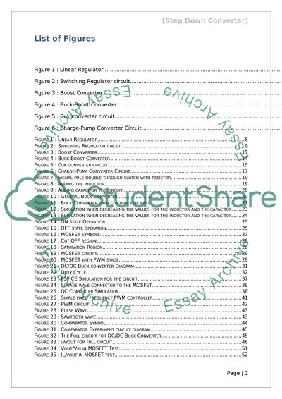
Summary Acknowledgment Table of contents Contents List of Figures 2 Chapter1. Introduction 3 1Introduction 3 2Why use a switching regulator? 5 6 1.3Type of DC/DC converters 8 1.3.1Non Isolated DC/DC converters 8 1.3.2Isolated DC/DC converters 9 Chapter 2: Various topologies for DC/DC Converter 10 2.1 Boost Converter 10 2.2 Buck-Boost Converter 12 2.3 Cuk Converter 13 2.4 Charge-pump converters 15 List of Figures Figure 1 : Linear Regulator 6 Figure 2 : Switching Regulator circuit 7 Figure 3 : Boost Converter 11 Figure 4 : Buck-Boost Converter 12 Figure 5 : Cuk converter circuit 14 Figure 6 : Charge-Pump Converter Circuit 16 Figure 1 : Linear Regulator 8 Figure 2 : Switching Regulator circuit 9 Figure 3 : Boost Converter 13 Figure 4 : Buck-Boost Converter 14 Figure 5 : Cuk converter circuit 15 Figure 6 : Charge-Pump Converter Circuit 17 Figure 7 : Signal-pole double-through switch with resistor 19 Figure 8 : Adding the inductor 19 Figure 9 : Adding capacitor the circuit 20 Figure 10 : General Buck Converter 20 Figure 11 : Buck Converter with control feedback 21 Figure 12 : Simulation when decreasing the values for the inductor and the capacitor 23 Figure 13 : Simulation when decreasing the values for the inductor and the capacitor 24 Figure 14 : ON state Operation 25 Figure 15 : OFF state operation 25 Figure 16 : MOSFET symbols 27 Figure 17 : Cut OFF region 28 Figure 18 : Saturation Region 28 Figure 19 : MOSFET circuit 29 Figure 20 : MOSFET with PWM stage 29 Figure 21 : DC/DC Buck converter Diagram 31 Figure 22 : Duty Cycle 32 Figure 23 : PSPICE Simulation for the circuit 37 Figure 24 : Square wave connected to the MOSFET 38 Figure 25 : DC Converter Simulation 38 Figure 26 : Simple fixed frequency PWM controller 41 Figure 27 : PWM circuit 42 Figure 28 : Pulse Wave 43 Figure 29 : Sawtooth wave 43 Figure 30 : Comparator Symbol 44 Figure 31 : Comparator Experiment circuit diagram 45 Figure 32 : The Full circuit for DC/DC Buck Converter 45 Figure 33 : layout for full circuit 46 Figure 34 : Vout/Vin in MOSFET Test 51 Figure 35 : IL/vout in MOSFET test 52 Chapter1. Introduction 1.1 Introduction Nowadays in almost all low current industrial applications, DC voltage is applied either by increasing or decreasing its values as per requirements. To achieve desired DC voltage level DC/DC converters are used that can convert a fixed input DC voltage from a DC source to either fixed or variable output DC voltage. Analogous to a transformer, a DC converter can also be used to control the output DC voltage level either by increasing or decreasing input DC level. In nature DC/DC converters involves electronic circuitry that can change efficiency of DC power to various levels. Following are few examples where DC/DC converters are used to change the output DC voltage levels: 1- In laptop generally the battery charger provides 18.5 V DC voltages to the laptop while its motherboard just needs 3V DC voltage. The desired voltage level is obtained by using DC/DC converter that steps down 18.5 V DC voltages to 3V DC level. 2- In the latest CPU chips 2V or less is required operating DC voltage level; where 1.5 V from a signal cell must be stepped up to 5V or more to operate electronic circuitry. In above given applications, DC/DC converters are applied to change the DC voltage from one level to another, with losing as little power as possible that is conversion takes place with optimum efficiency. Since transformers simply step up or step down the voltage levels hence they cannot be used instead of DC/DC converters as they change the input energy into a different impedance level besides stepping up or stepping down the voltage levels. It implies that DC/DC converts can manage the required power levels irrespective of output voltage level. DC/DC Converters are divided into four major types that include: 1- Buck Converter. 2- Boost Converter. 3- CUK Converter. 4- Buck and Boost Converter. The division has been made depending in the present between the output and the input values. The Boost converter has higher output voltage values as compared to input while vice versa for the buck converter. Buck and Boost Converters are particularly useful in situations where both ‘Higher and Lower output’ values are required. The objective of this project work is to study and analyse the ways and techniques of control the output voltage by applying of DC/DC converters and based on this study outcomes design a DC/DC Buck converter circuit that has numerous industrial applications. Statement of objectives The project work has following major objectives: 1- To understand the operation of each type for DC/DC Converter, DC chopper circuits and MOSFET. 2- To examine and investigate the methods of controlling the output voltage of DC-DC converters. 3- To consider Pulse Width Modulated (PWM) with the converters. 4- Design a DC-DC Converter the circuit and test it on PSPICE. 5- Construct the circuit on breadboard and again test it for its required operation. 6- To study the feedback controller. 7- In view of feedback design construct and test the final DC-DC Converter circuit design. 8- Compare and analyse the theoretical and practical results obtained through this project work. 1.2 Why use a switching regulator? Earlier the voltage regulation generally had been done by applying Linear Regulators yet with the development of switching regulators, regulation is now is carried through the application of switching regulators particularly far better efficiency of switching regulators as compared to their linear counterpart. A comparison of efficiency of both types is given below. Let we consider the linear DC voltage regulator as shown in fig. 1 given below. Figure 1 : Linear Regulator Let assume that = 12V and =6V. =10 A. i.e. there is 6 V voltage drop across the regulator. Now as: (Eq. 1.1) Substituting the values of Vout and Iout in equation 1.1, we have; It implies that regulator must dissipate 60W energy into heat that is 50% reduction in efficiency in terms of input energy. Additionally to take away the heat generated, heat sinks are used that increase the size of linear regulator and hence makes then inappropriate to use where the efficiency and size are important parameters [1]. On the other hand let consider a switching regulator as shown in fig. 2 given below; Figure 2 : Switching Regulator circuit Let we assume that regulator is on and off at a fixed rate (usually between 50-100 KHz). Then as the Duty cycle is defined by equation: (Eq. 1.2) Compared to linear regulators (with 50% to 60% efficiencies), the efficiencies of the Switching regulator are high (80% to 95%) for assume frequency changes. Hence in case there is little energy loss in form of heat and we required very small size heat sink to take away that heat – an obvious advantage when size and efficiencies area important constrains in design. Additionally by using Switching Regulator we get advantage of energy stored by inductor and capacitor can be transformed to output voltage and also we can step up or down the input the input voltage by using switching Regulators that is not possible with linear regulators. Table-1 gives a brief comparison of various features of both types of regulators [2]: Linear Regulator Switching Regulator Function Step down the voltage Step up, down, or invertors Complexity Low, comprise generally only the regulator and low value by pass capacitors. Medium to high, it uses inductor, diode and filter capacitor. size Small to Medium, it can be larger if heat sink is needed Larger at low power, but at higher power it will be smaller for which linear regulator needs heat sink Cost Low High Ripple/ noise Low Medium to high because of external components Waste heat Low to Medium High Table 1: Comarsion between Linear and Switching Regulator [2] 1.3 Type of DC/DC converters DC/DC converters are divided into two major categories: Non Isolated DC/DC converters. Isolated DC/DC converters. 1.3.1 Non Isolated DC/DC converters The non- isolated converter design usually involves an inductor as its major component. As obvious from the type name such invertor does not have dc voltage isolation between the input and the output as the majority of applications of do not require dc isolation between output and input voltages. It is generally used to either step up or step down the voltage with a very nominal ratio (4:1). Non isolated DC/DC converters take their input generally from battery-based systems which don’t use the ac power line. Another application of the non-isolated DC/DC converter is its use as a point-of-load DC/DC converter. A point-of-load DC/DC converter extracts its input power from an isolated DC/DC converter, like a bus converter. The non- isolated converter have five main categories as mentioned below: Buck converter. Boost Converter. Buck-Boost Converter. Cuk Converter. Charge-pump converters. 1.3.2 Isolated DC/DC converters As obvious from their name in isolated DC/DC convertors ac input that is directly fed from ac power lines is isolated from dc output by using an isolation transformer. Depending on applications, generally the typical isolation voltage for DC-DC power supply runs from 1500V to 4000V. Apart from isolation between ac input and dc output, isolation transformer also eliminates the dc path between the two. [1] Chapter 2: Various topologies for DC/DC Converter DC/DC converters have a verity of types. The main objective of each type is to change the output voltage level. The following chapter will address in details the major types of DC/DC converters, their configuration and operation. DC/DC converters can be categorized into different categories either on the basis of their operation or their applications. In view of their operation, DC/DC converters can change the voltage level at input, at output or at both ends by stepping up/down the voltage. In view of their applications, DC/DC converters have following major categories: Boost Converter Buck Boost Converters Cuk Converters Buck Converter. Following section gives a brief discussion of each type DC/DC converters. 2.1 Boost Converter DC/DC Boost converters comprises of following major circuit components as shown in fig. 3 on next page. Switching Power MOSFET Q1. Flywheel diode D1. Inductor L. Output filters capacitor C. Generally the single IC based switching and control unit of Boost converts function is to switch and monitor the output voltage at required level. This function is carried out through the application of the MOSFET. By switching on and off at fixed frequency, MOSFET controls the voltage at desired level. When MOSFET is switched on by changing the duty cycle, current flows from source through the inductor L and energy is stored in the inductor in the form of magnetic field. The resultant field will oppose the further input current and there will not flow of further current through the inductor. The load is current is supplied and compensated by the charge in the capacitor. Also as the MOSFET is switched off, there is a sudden decrease in input current at inductor. Since inductor opposes any sudden drop in current by immediately reversing its EMF, the reversing of EMF will boost the source voltage results a flow of current from the source through the inductor. Due to the flow of current, the output capacitor will recharge from the current flowing through the flywheel diode and the load. As a result all this operation, the level of voltage at output side will be boost up. The resultant step up voltage ratio in term of duty cycle can be calculated by applying following relation: (Eq. 2.1) Also, (Eq. 2.2) From equation 2.1, if we step up the voltage in 3: 1, then the resultant duty cycle is 66%. If we assume 100% efficiency of the converter then the ration between input and output current will be equal to the ratio of voltage levels at input and output sides as given below: [3] (Eq. 2.3) Figure 3 : Boost Converter 2.2 Buck-Boost Converter The basic component configuration of the Buck-Boost converters is similar to the boost converters and the buck converters (that will be discuss in coming section) with different working criterion. Contrary to boosting only the output voltage, the Buck-Boost convertors can both step up and step down the output voltage levels by changing the duty cycle. Figure 4 : Buck-Boost Converter Similar to the Boost converters as we switched on the MOSFET, a flow of current from source to inductors is observed. The flow of current through inductor will result a magnetic field and an EMF will be produce in the inductor circuit. The EMF produced will result storage of energy due to magnetic field. During this process as diode is in reverse mode of operation hence there will be no flow of current through diode while the load current is only supplied through the charge stored in the capacitor. Also as the MOSFET is switched off, there is a sudden reduction of flow of current from source to inductor. Since inductor will oppose a sudden change in current by reversing its magnetic field. The reversal of magnetic field will compensate the source voltage and hence will keep away the current from dropping. As during this process, diode is in forward biased mode results a flow of current into the load. For the Boost-Buck convertors, the ratio between the output voltages in terms of duty cycle is defined as: (Eq. 2.4) This is also equal to: (Eq. 2.5) From above discussion it is obvious that duty cycle plays the key role in controlling the output voltage level. Hence if we select duty cycle less than 50% then the resultant output will be step down and vice versa. Another important feature of Buck-Boost converters is that they can be used as voltage inverter as during their operation, the output of converters always has opposite polarity i.e. output voltage is always inverted with respect to input voltages. The Buck-Boost inverters features to step up or step down the output voltage levels along with output voltage inverting characteristic make them an important component of many industrial applications. [3] 2.3 Cuk Converter Compared to Boost, Buck-Boost and Buck converters (discussed later), Cuk converters circuit configuration is looked like a combination of Boost and Buck-Boost converters. Opposite to both Boost and Buck-Boost converters, Cuk converters utilized dual inductors (L1, L2) and dual capacitors (C1, C2) as shown in circuit diagram 5. Similar to Buck-Boost converters, Cuk converters also invert the output voltage level compared to input. During converters operation as high ripple current generally flows through C1 so usually C1 is made up of a large electrolytic that can sustain a high ripple current rating and low ESR to minimise loss. Figure 5 : Cuk converter circuit During operation, as the MOSFET Q1 is switched on, a flow of current will occur through the inductor resulting a magnetic field and hence an induced EMF. Due to induced EMF, energy will be stored in inductor. Since during the flow of current from source the diode is in forward biased mode, it will charge the capacitor C 1. Now as the MOSFET Q1 is switched off, inductor will oppose a sudden change in current by reversing its field and maintaining the input source voltage. As during on operation capacitor C1 is charged so it will discharge and enhance the output voltage results a higher output voltage value compared to its input value. [3] Now if the MOSFET Q1 is again switched on then as the capacitor C1 is discharging through the inductor L2 into the load then sudden application of input voltage is smooth out through capacitor C 2 that acts as a filter. In the meantime energy stored again in the inductor L1 and becomes ready for the next cycle. For Cuk the ratio between the output voltage and input voltage in terms of duty cycle and Ton and Tout is given as: (Eq. 2.6) Comparing equation 2.4, 2.5 with equation 2.6, as ratio between output and input voltage is same as that of Buck-Boost converters so Buck-Boost converters can also be used as Cuk converters and vice versa. The minus sign in equation 2.6 indicates the inversion of output voltage with respect to input voltage. The Cuk converter is similar in operation as that of Buck-Boost coverts as we can change the level of output voltages by varying the duty cycle. The only major difference between two types is the presence of current ripples in Cuk converters because of presence of the series inductors at both input and at load end. 2.4 Charge-pump converters Compared to Boost, Buck-Boost and Cuk converters, Charge-pump converters are based on different operation principle. As Boost, Buk-Boost and Cuk converters utilize the energy stored in inductors to change the output voltage levels yet Charge-pump converters change the output voltage level through the energy stored in the capacitor. The basic circuit configuration of Charge-pump converters consist of traditional voltage doubling and voltage multiplying rectifier circuits as shown in figure 6. From circuit diagram it is obvious that Charge-pump converters consist of; 1- A Bucket capacitor C1 2- Four MOSFET Q1, Q2, Q3 and Q4 switches. 3- A switching control unit For operation purposes as voltage is applied at input side the MOSFET Q1 and Q4 are switched and Bucket capacitor C1 that is directly connected to the input source voltage, begins to charge. Now if we switch off, MOSFET Q1 and Q4 and switch on MOSFETs Q2 and Q3 then this will bring C1 in series with input voltage source and across output reservoir charged capacitor C2 hence an amount of charge in Capacitor C1 travels to capacitor C2 that which will lead to twice the input voltage. It implies that during operation process as Q2 and Q3 is switched off; the decrease in current is compensated through the charge stored in capacitor C2. Since a heavy ripple current flows through the Cuk converter circuit, so both capacitors must have reasonable vales to sustain the ripple current. Figure 6 : Charge-Pump Converter Circuit An important application of Charge-pump converters is their use as inverter circuits. For such applications, Charged- pumped converter circuit is little bit modify, that gives an inverted output voltage having same value as that of applied voltage. Hence Charged-pump converters are used to generate a negative supply rail electronic circuits running from a single battery. Economically these converters are low cost and more compact than inductor-type converters. [3] Read More
Tags
Cite this document
  • APA
  • MLA
  • CHICAGO
(Ways and Techniques of Control the Output Voltage by Applying of DC/DC Coursework Example | Topics and Well Written Essays - 3000 words, n.d.)
Ways and Techniques of Control the Output Voltage by Applying of DC/DC Coursework Example | Topics and Well Written Essays - 3000 words. https://studentshare.org/engineering-and-construction/1797816-dc-to-dc-buck-converter
(Ways and Techniques of Control the Output Voltage by Applying of DC/DC Coursework Example | Topics and Well Written Essays - 3000 Words)
Ways and Techniques of Control the Output Voltage by Applying of DC/DC Coursework Example | Topics and Well Written Essays - 3000 Words. https://studentshare.org/engineering-and-construction/1797816-dc-to-dc-buck-converter.
“Ways and Techniques of Control the Output Voltage by Applying of DC/DC Coursework Example | Topics and Well Written Essays - 3000 Words”. https://studentshare.org/engineering-and-construction/1797816-dc-to-dc-buck-converter.
  • Cited: 0 times

CHECK THESE SAMPLES OF Ways and Techniques of Control the Output Voltage by Applying of DC/DC Converters

Low Voltage Stabilized Power Supply

The mulitmeter can then be set to dc voltage so that the voltage can be calculated at points A, B, C, and E in relation to point D.... Also, the multimeter was set to a dc current measurement.... A key requirement of a stabilized power supply is that its output is maintained at constant voltage and is does not react to load current… Low-voltage output is put into points X & Y from the mains transformer after checking that the link connectors arecorrectly connected to the board in the right manner....
2 Pages (500 words) Essay

Lab report in DC Voltage Regulators

A linear voltage is regulator is often used to create a known voltage using a transistor which operates in the regulator's forward active… A voltage regulator can therefore be defined as a gadget which creates an output voltage which is steady, clean and of known value under varying conditions including load impedances/load currents, varying Typically, Zener diodes are intended to offer constant output voltage to a given load connected parallel to it irrespective of the variations in voltage supply or load current fluctuations....
5 Pages (1250 words) Assignment

Reactive Power Compensation Using Photovoltaic Inverter

The structures are static converters that are capable of exchanging active power between an energy source or an energy storage device (capacitor at night).... Both reactive and active powers are controlled by the dc Capacitor and inverter output voltages.... The development of this regulation structure for active power filter is employed when combining with other structures that are to be connected in dc link bus.... At the inverter's dc side, there is a capacitor that stabilizes proper voltage level for better operation of the inverter that acts current source....
3 Pages (750 words) Assignment

Three-Unit Electromagnetic Generator Control

three unit generator control system protects the generator by preventing overheating and ensures that it can be more reliable by allowing for frequent adjustments to the output of the generators.... A dc generator produces current that flows in a constant direction as opposed to the alternating current which periodically reverses direction.... A dc generator produces current that flows in a constant direction as opposed to the alternating current which periodically reverses direction....
1 Pages (250 words) Essay

Alternative Current vs Direct Current

Alternative current won over direct current in the 20th century when it was chosen over dc because people considered it more reliable, it had very few risks and this is why, it was chosen as the standard current in North America; dc, on the other hand, had several major issues which were later sorted out and fixed.... After fixing the major issues with dc, several European countries chose it as their standard current; these days dc is being used in some of the elite European countries....
7 Pages (1750 words) Essay

Calculating the Operating Parameters of the DC-DC Boost Converter for Automobile Electronics

"Calculating the Operating Parameters of the dc-dc Boost Converter for Automobile Electronics" paper defines the features of the dc-dc converter, as well as reveal the detailed project development and implementation.... Specifications of the design are explained from the perspective of circuit usability… The current project involves developing and calculating the operating parameters of the dc-dc boost converter for automobile electronics....
6 Pages (1500 words) Coursework

Amplification and Analogue to Digital Converters

The paper "Amplification and Analogue to Digital converters" states that the performance of the system was according to the expectations.... The Capacitive voltage Transformer (CVT) is a voltage Transformer (VT) with a capacitive divider that converts input to a CVT.... The high voltage capacitors also serve as carrier current coupling.... The detected current is further converted to a signal called a differential voltage signal through the help of a load resistor....
7 Pages (1750 words) Case Study

Continuous and Discrete-Time PID Control of DC Motor Position

This assignment "Continuous and Discrete-Time PID Control of dc Motor Position" discusses digital control applications that are highly applied and used in modern applications, which is mainly related to the easy control the individual has on the applications and performance attainable.... That is; if the parameters are chosen incorrectly, the output is also unstable.... The noise changes the output quantity received thus affects the performance of the system....
6 Pages (1500 words) Assignment
sponsored ads
We use cookies to create the best experience for you. Keep on browsing if you are OK with that, or find out how to manage cookies.
Contact Us