StudentShare
Contact Us
Sign In / Sign Up for FREE
Search
Go to advanced search...
Free

Fluid Mechanics for Engineers - Lab Report Example

Cite this document
Summary
The lab report "Fluid Mechanics for Engineers" involves the analysis of the energy losses in pipes. The main focus of this experiment is to study the head losses that are experienced through common fittings and valves which are commonly found in piping systems…
Download full paper File format: .doc, available for editing
GRAB THE BEST PAPER96.3% of users find it useful
Fluid Mechanics for Engineers
Read Text Preview

Extract of sample "Fluid Mechanics for Engineers"

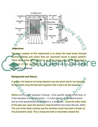
 Summary This lab experiment involves the analysis of the energy losses in pipes. The main focus of this experiment is to study the head losses that are experienced through common fittings and valves which are commonly found in piping systems. The equipment necessary for this work to be carried out will be collected and assembled as provided in the lab manual. The piping system will be conducted as provided for in the instructions. Since the two tests cannot be carried out at the same time, this must be accomplished in two segments which are outlined in the experimental procedure as exercise A and B. the results have been obtained for three different runs and this will be important in obtained different results that will be crucial for computation of the different values of K loss coefficient. The data obtained will also be used to plot a graph of head loss Versus Dynamic Head. The extent of the errors will then be computed in order to determine the accuracy of the data obtained. Finally, the values computed will be compared against the values given in the textbooks and the observations made recorded. Introduction Energy losses in pipes normally result from friction that occurs between the walls of the pipe and the fluid and the internal friction in the particles of the fluid. On the location of the pipe whereby the streamlines are not straight such as the bends, piping junctions, valves contraction and expansion joints and the inlets and outlets of the reservoirs, minor head losses are experienced (Fluid mechanics: Online). In this experiment, we are going to measure the minor head losses through a section of pipe with a number of transitions, fittings and bends as shown in the figure below: Figure 1: Diagram for the apparatus set up Objectives The main purpose of this experiment is to study the head losses through common fittings and valves that are commonly found in piping systems. These head losses are referred to as minor losses and can be evaluated in the form of loss coefficient KL and compared with the theoretical values given in the textbook. Background and theory  In a pipe, the balance of energy between any two given points can basically be described using the Bernoulli equation that is given by the equation: Where pi is the static pressure in Pascal, is the specific weight of the fluid, z1 is the elevation in meters of point i , Vi is the velocity of the fluid at point i and g is the gravitational constant and hL is head loss. gives the static head of the pipe and gives the dynamic head (Armfield Instruction Manual, 2004). The sum of the static velocity and the elevation result into what is known as the piezometric head. This is measured with a manometer aboard the apparatus of this experiment. The head loss of the piping is the summation of the friction loss in the pipe and all the other existing minor losses. This can be written as shown in the equation below: Where is the minor head loss in meters to the ith term, n is the number of valves and fittings and hL is head loss. The friction experienced in the pipe can be given by the Darcy-Weisbach equation as shown below: Where f is the friction factor, L is the pipe length and D is the diameter of the pipe (Rainer & Baade, 2012). In this experiment, it shall be assumed that the losses due to friction in the pipe are negligible. As discussed earlier, the losses normally occur at the location of the pipe whereby the streamlines are not straight such as the bends, piping junctions, valves contraction and expansion joints. For all the components that will be used in this experiment, the head loss will be given by the equation: Where is the dimensionless loss coefficient for the ith component and V is is the velocity of the fluid travelling through the pipe. In this lab experiment, the coefficients of loss for the different components that will be involved in the piping system will be determined experimentally by computing the values using the equation given above for the head loss and the loss of coefficient. In part B of the lab experiment, we shall measure the pressure difference across agate valve using the pressure gauge in bars. Equipment a) Hydraulics Bench which allows for the measurement of flow using timed volume collection. b) Energy Losses in Bends and Fittings Apparatus. c) Stopwatch to allow the determination of the flow rate of water. d) Clamps for pressure tapping connection tubes. e) Spirit level. f) Thermometer. Technical data Internal diameter of the pipe work d = 0.0196 m Internal diameter of pipe work at enlargement outlet and contraction inlet d = 0.0260 m Experimental procedure 1) The losses apparatus are set up on the hydraulic bench such that the base is horizontal. The test rig inlet is connected to the bench flow supply and the outlet extension tube is run to the volumetric tank and secured in place. 2) The bench valve, the gate valve and the flow control valves are opened and the pump is started in order to fill the test rig with water. In order to bleed air from the pressure tapping points and the manometer, both the bench valve and the test rig flow control valves are closed. The air bleed screw is opened and the cap that is adjacent the air valve is opened. A length of the small ball tubing is connected to the volumetric tank from the air valve. The bench valve is then opened and allows the flow of water through the manometers to purge all the air from them. The air bleed screw is tightened and both the bench valve and the test rig flow control are partly opened. Finally, the air bleed screws are slightly opened in order to allow the flow of air to the top of the manometers. The screws are retightened when the manometer finally reaches a convenient height. 3) Next, all the manometers levels should be checked on a scale so that they are at a maximum volume flow rate of approximately 17 liters per minute. These levels can be adjusted using the air bleed screw and the hand pump that will be supplied in the lab. Experimental exercise A 1) The loss across all the pipe fittings is measured except at the gate valve which must be left fully open. The flow from the bench control valve is adjusted and at a given rate of flow, the height readings are taken from all the manometers. 2) To determine the volume flow rate, a timed volume collection is carried out using the volumetric tank. This can be achieved by closing the ball valve and measuring with a stop watch the time taken to accumulate a known volume of fluid in the tank which is read from the sight glass. 3) The fluid should be collected for at least 1 minute in order to minimize the time errors. This procedure is then repeated to a total of at least five sets of measurements over the flow range of approximately 8-10 liters per minute. The outflow water temperatures are measured at the lowest flow rate Experimental exercise B 1) The loss across the gate valve only is measured. The connecting tube to the miter bend pressure taping is then clamped off in order to prevent the air from being drawn into the system. 2) The gate valve is closed and then both the bench valve and the test rig flow control valve are opened fully. 3) The gate valve is then opened fully by approximately when it is turned 1 time only. For each of at least 5 flow rates, measure pressure drop across the valve from the pressure gauge; adjust the flow rate by the use of the test rig flow control valve. Once measurements have started, do not adjust the gate valve. 4) Determine the volume flow rate by timed collections. 5) Repeat this procedure for the gate valve opened by approximately 2 turns as well. Result and calculations Calculations Meter: Elbow: Short Bend: Enlargement: Contraction: The rest of the data that was obtained from this experiment is as shown in the tables below. Table 1: The calculated data for run #Run 1 Trial #1 Fitting h1 (m) h2 (m) ∆ h (m) Q (m3/sec) V1 (m/s) V2 (m/s) Meter 3.26E-01 3.10E-01 1.60E-02 0.000143 0.4744 0.269592 Elbow 3.52E-01 3.36E-01 1.60E-02 0.000143 short 3.66E-01 3.56E-01 1.00E-02 0.000143 Enlarg 3.71E-01 3.74E-01 -3.00E-03 0.000143 contraction 3.74E-01 3.64E-01 1.00E-02 0.000143 0.26959 0.474396 Table 2: The calculated data for run #Run 1 Area1 (m2) Area2 (m2) V2/2g (m) ∆ h (m) ki,p 0.000302 0.000531 0.01147 1.39488 0.01147 1.39488 0.01147 0.8718 0.01147 4.77E-03 0.41551 0.0037 1.78E-02 4.796 Table 3: The calculated data for run #Run 2 Trial #2 Fitting h1 (m) h2 (m) ∆ h (m) Q (m3/sec) V1 (m/s) V2 (m/s) Meter 2.66E-01 2.42E-01 2.40E-02 0.000193 0.64057 0.364027 Elbow 3.26E-01 2.83E-01 4.30E-02 0.000193 short 3.25E-01 3.10E-01 1.50E-02 0.000193 Enlarg 3.34E-01 3.40E-01 -6.00E-03 0.000193 contraction 3.38E-01 3.24E-01 1.40E-02 0.000193 0.36403 0.640572 Table 4: The calculated data for run #Run 2 Area1 (m2) Area2 (m2) V2/2g (m) ∆ h (m) ki,p 0.000302 0.000531 0.02091   1.14756     0.02091   2.05604     0.02091   0.71722     0.02091 0.00816 0.39016     0.00675 2.82E-02 4.1693 Table 5: The calculated data for #Run 3 Trial#3 Fitting h1 (m) h2 (m) ∆ h (m) Q (m3/sec) V1 (m/s) V2 (m/s) Meter 2.34E-01 2.04E-01 3.00E-02 0.000204 0.67582 0.384058 Elbow 2.75E-01 2.56E-01 1.90E-02 0.000204 short 3.00E-01 2.83E-01 1.70E-02 0.000204 Enlarg 3.33E-01 3.14E-01 1.90E-02 0.000204 contraction 3.13E-01 2.95E-01 1.80E-02 0.000204 0.38406 0.675821 Table 6: The calculated data for #Run 3 Area1 (m2) Area2 (m2) V2/2g (m) ∆ h (m) ki,p 0.0003 0.000531 0.02328   1.28872     0.02328   0.81619     0.02328   0.73027     0.02328 0.034761 1.49324     0.00752 3.38E-02 4.49078 Graph 1: Variation Head loss Versus Dynamic Head The slopes shown in the graph represent the K value for every fitting Since we plotted ∆h Vs. And slope equation given by Where: y= ∆h x= Then, a= K (head loss coefficient) Error Analysis 1. Calculating Kavg as the following equation 2. Calculating standard deviation: Data for the Kavg and standard deviation for the fittings are listed in the following table. Table 7: Average K for fittings and standard deviation error Fitting Kaverage SDk SDk,m METER 1.277051 0.124074 0.071634 ELBOW 1.422369 0.620384 0.358179 SHORT BEND 0.773098 0.085727 0.049494 ENLARGEMENT 0.222181 0.313164 0.180805 CONTRACTION 4.818694 0.861503 0.497389 Calculating percentage error: Table 8: Percentage Error for approximated values for K and real values of K Fitting Kavg (Calculated) Real Value %Error meter 1.277051 0.7 82.4359 elbow 1.422369 0.7 103.196 short bend 0.773098 0.2 286.549 Enlargement 0.222181 0   contraction 4.48536 0   The actual values of K are taken from the following Table. Table 9: Loss Coefficient K for different pipes and fittings Discussion From the graph and the analysis carried out above, it is evident that the pressure differences in the enlargement and the long bend sections of the piping systems have a great degree of similarity. The contraction section is very close to the line. A comparison of the computed results for the loss coefficient in the different sections of the piping system that have similar results, it can be seen that the computed results are only similar in a few sections. In the meter section, the average value of K obtained is 1.277051 which is close to the value given in the textbook at 1.2. For the elbow section, an average value of 1.422369 was obtained and this falls within the range of values for the elbow given in the textbook which run from 0.2-1.5. An average value of 0.773098 was obtained for the short bend and an average value of 0.222181 was obtained for the enlargement. For the contraction, an average value of 4.48536 was obtained. The average uncertainty of the results is 82.4359% for the meter, 103.196% for the elbow and 286.549% for the short bend. The results obtained in this experiment raise a number of issues in regard to the time of the day when it was conducted. If it was conducted early in the morning when the water temperatures could have been below 20°C, this would have increased the velocity and this would have had a greater impact on the results (Fluid mechanics: Online). Similarly, if the experiment was conducted at midday when the temperatures are high, the velocity of the water would have been lower (Rainer & Baade, 2012). It is also important to point out that the roughness of the internal surface of the pipes could have had a great effect on the obtained results. The possible sources of errors during this experiment could have been the shear stress experienced between layers of the liquid and the piping system and the ignoring of the elevation between different components. It is also important to take into consideration the effects of the density of the water as it expands and contracts within the piping system (Strothman, 2006). Conclusion From the experiment carried out above, the K head loss coefficient of the piping system has been determined. The results have been presented in the sections above as computed values of K coefficients. The results obtained were compared to the values given in the text book and the differences and similarities noted and outlined in the sections above. For future works, it is recommended that spreadsheets with pre loaded formulas should be used to compute for the values of K. This will make the work analysis easier and more accurate. References Fluid mechanics. Retrieved from: http://nptel.iitm.ac.in/courses/Webcourse-contents/IIT-KANPUR/FLUID-MECHANICS/lecture-37/37-2_losses_pipe_bends.htm accessed on 2nd June 2015. Armfield Instruction Manual, Losses in the bends F1-22, March 2004. Rainer, E., Baade, H.J., 2012, “Water density determination in high-accuracy flowmeter calibration– Measurement uncertainties and practical aspects”, Flow Measurement and Instrumentation Journal,vol. 25, pp 40-53. Strothman, J., 2006, “ISA Handbook of Measurement Equations and Tables (2nd Edition)”, ISA Online version available at: http://app.knovel.com/hotlink/toc/id:kpISAHMET1/isa-handbook-measurement Read More
Cite this document
  • APA
  • MLA
  • CHICAGO
(Fluid Mechanics for Engineers Lab Report Example | Topics and Well Written Essays - 2328 words, n.d.)
Fluid Mechanics for Engineers Lab Report Example | Topics and Well Written Essays - 2328 words. Retrieved from https://studentshare.org/engineering-and-construction/1696859-energy-losses-in-bends-fluid-mechanics-for-engineers
(Fluid Mechanics for Engineers Lab Report Example | Topics and Well Written Essays - 2328 Words)
Fluid Mechanics for Engineers Lab Report Example | Topics and Well Written Essays - 2328 Words. https://studentshare.org/engineering-and-construction/1696859-energy-losses-in-bends-fluid-mechanics-for-engineers.
“Fluid Mechanics for Engineers Lab Report Example | Topics and Well Written Essays - 2328 Words”, n.d. https://studentshare.org/engineering-and-construction/1696859-energy-losses-in-bends-fluid-mechanics-for-engineers.
  • Cited: 1 times

CHECK THESE SAMPLES OF Fluid Mechanics for Engineers

My life An Engineer

Part of my undergraduate degree included coursed in Engineering Drawing; Tribology; fluid mechanics; Strength of Materials and Dynamics; Thermodynamics; Automatic Controls; Mechanical Vibration and Principle of Engineering Design amongst others.... My Life; an Engineer Engineering is a very competitive profession since it does not only depend on how much on can do but also on how much knowledge one has....
3 Pages (750 words) Essay

How has Human Civilization Advanced Because of our Knowledge of Fluid Mechanics

In fluid mechanics, Civil engineers try to solve problems in floods by constructing better bridges and roads; they solve drainage problems by designing proper sewage… fluid mechanics is the study of fluids and the forces behind them.... fluid mechanics works hand in hand with hydraulics and has existed for a long time.... Engineers also use fluid mechanics in aerodynamics when designing planes, ships, trains, and cars, designing mechanical systems such as engines and machines and town planning (Braben 45)....
5 Pages (1250 words) Essay

Three Most Significant Applications of Fluid Mechanics

This paper "Three Most Significant Applications of fluid mechanics" focuses on the fact that the first significant application of fluid mechanics is in aerodynamics.... Therefore, fluid mechanics has played an important role in aerodynamics.... The second application of fluid mechanics is in turbulence modelling.... The present research has entirely focused on exploring fluid mechanics and undertaking complex turbulence modelling....
1 Pages (250 words) Essay

Rotational Viscometer

fluid mechanics study how fluids react to a different force.... For example, the environmental engineers use it to study forest fires, pollution dispersion, weather patterns that aid in weather forecasting, oceanography and volcano behavior.... engineers design equipment that use fluids, transport or operate in fluid environments such as pacemakers and engines.... The rotational Viscometers work under different mechanics depending on their design and the fluid On the other side, the importance of fluids having different properties will be looked at from the angle of engineering by relating the viscosity of different fluids to the ability to work....
6 Pages (1500 words) Essay

Use of Modeling and Simulation in the Design of the Boeing 777

All changes to the concept had to be done on the same CAD model which allowed other engineers to see how their own parts would fit in.... The CATIA models of individual components and subsystems would be built up into the aircraft model and the engineers could visualize issues like fits and tolerances, access for assembly and dismantling, routing of cables and pipes and other such details which were done with physical mockups earlier.... With the EPIC system, he could fine tune his design multiple times until there was a “freeze” to permit the tooling or manufacturing engineers to proceed with their design activity....
2 Pages (500 words) Essay

Automated Sprinkler

Thus, the engineering design process helps engineers and other problem-solvers to come up with creative solutions to everyday problems.... Through the application of ingenious engineering principles, engineers offer solutions to the many day-to-day challenges that require engineering knowledge....
5 Pages (1250 words) Essay

Water Filled Radiator for Domestic Heating

The radiator also emits a combination of radiant and convected heat to ensure that the whole room becomes warm (American Society of Heating and Ventilating engineers, 2008).... This may take place in order to cool the fluid entering the radiator, such as in engines, or to heat the environment....
6 Pages (1500 words) Assignment

Flow over Sharp-Crested Weirs

Measurement of fluid flow has been historically been performed with the use of weir device (John, 2000).... To perform the examination of the nature and action of pressure forces around as well as on the rectangular weirs Theory Measurement of fluid flow has been historically been performed with the use weir device (John, 2000).... In this types of weirs, the fluid flowing changes into an overflowing water sheet which is known as a nappe....
12 Pages (3000 words) Research Paper
sponsored ads
We use cookies to create the best experience for you. Keep on browsing if you are OK with that, or find out how to manage cookies.
Contact Us