StudentShare
Contact Us
Sign In / Sign Up for FREE
Search
Go to advanced search...
Free

Circuit Project 2 - Lab Report Example

Cite this document
Summary
The methods are simulation with ODE, Powersim toolbox and Simulink and State Space block (Brian, 27). The output demonstrates the variation of the electric…
Download full paper File format: .doc, available for editing
GRAB THE BEST PAPER94.2% of users find it useful
Circuit Project 2
Read Text Preview

Extract of sample "Circuit Project 2"

Lab Report, Engineering and Construction Circuit Project 2 Simulation Simulation The equations are xn = Ax + BU and y = Cx + Du 1.1. Source Code% Function definitionFunction [xdot] = trans_analysis(tim, xn) xn1 = zeros (4, 2); xn1 = [xn(1); xn(2); xn(3); xn(4)]; Ln1 = 1.4; Rn1 = 3300; Ln2 = 0.15; Cn1 = 51e-6; Cn2 = 14e-6; un = 150 * sin(10 * tn); Ax = [0 1 1 0;(-Ln2 - Ln1) / (Ln1 * Ln2 * Cn1) (-Rn1 * Ln2 - Rn1 * Ln1) / (Ln1 * Ln2) – 1 / (Ln2 * Cn2) 0; 0 0 1 1;-1 / (Ln2 * Cn1) -Rn1 / Ln2 -1 / (Ln2 * Cn2) 0]; Bx = [0; (Ln2 + Ln1) / (Ln1 * Ln2);0;1 / Ln2];Un = un;xn = A * xn1 + B * U; Calling Functions File t0 = 0; tnf = 3;tn_interval = 0.

10; xn0 = [0;1;1;0]; tspan = t0: tn_interval:tf; [tn, xn] = ode22(trans, tspan, x1); figure(1) plot(tn, xn(:,5),Tn / Xn) grid on title(circuit current) xlabel(Time - seconds) ylabel(Current Amp [A]) figure(2) plot(tn, xn(:, 5),Ks) grid on title( Current / Time) xlabel(Time seconds) ylabel(Current [Amps]) figure(3) plot(t, (xn (:, 5) - xn(:, 5)), ks) grid on title(Current / Time) xlabel(Time sec’) ylabel(Current [Amps])Y = C * x + d * U% first condition is ST; input and FT:yt = 0; Tn = 0.11; Nt = 15;ut = 5; %for ii = 0 : t : Nknt1 = Tnx * f (yy, t, tt);knt1 = Tnx * f (yt + knt1, ut, tNt + T);yt = yt + 0.

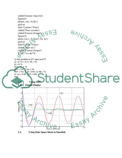
20 * (kt1 + kt2);end1.2.  Using ODE1.2.1. Output Display1.3. Using State Space block in Simulink1.3.1. Output Display 1.4. Building scheme applying Powersim toolbox1.4.1. Output DisplayFig 4: Current against Time2. Report2.1. Values of the ParametersThe parameters being used in the simulation are voltage, electric current, electric charge from the capacitors, resistance, power and time. The ranges of the values used are shown below:ParameterUpper LimitLower LimitVoltage (V)25Electric Charge - Te1020Electric Charge – Ti100200Resistance R11020Resistance R21020Time (Seconds)20302.2. IntroductionThe simulation of the electric circuit in this exercise takes three dimensions, each of which shows a unique result.

The methods are simulation with ODE, Powersim toolbox and Simulink and State Space block (Brian, 27). The output demonstrates the variation of the electric properties against time.2.3. Schematic Diagram 2.4. Comparison of the three ResultsThe first simulation shows three lines of voltage for Vx1, Vx2 and vx3. These are the three variables representing the voltage at different time and at different currents. Vx3 has the greatest amplitude followed by vx1 then finally vx2. The second simulation shows non linear relationship between the voltage and the time (Shailendra, 54) and (Khaled 38).

The bode plottting shows almost constant boud against the time variable then a decline from the midle to the end. Simulation 3 shows results in separate plotting for y1 and y2 in which the amplitude of the voltages are higher that in a separate y1 plotting.Works CitedBrian Su-Ming Fan, Modeling and Simulation of a Hybrid Electric Vehicle Using MATLAB/Simulink and ADAMS, NewYork: University of Waterloo, 2007. DepaRnment of Mechanical and Mechatronics Engineering, 2007.Shailendra, Jain, MODELING & SIMULATION USING MATLAB SIMULINK (With CD).

New Delhi: Wiley India Pvt. Limited, 2007Khaled M. Gharaibeh, Nonlinear Distortion in Wireless Systems: Modeling and Simulation with MATLAB, New York: John Wiley & Sons, 2011.

Read More
Cite this document
  • APA
  • MLA
  • CHICAGO
(“Circuit Project 2 Lab Report Example | Topics and Well Written Essays - 500 words”, n.d.)
Circuit Project 2 Lab Report Example | Topics and Well Written Essays - 500 words. Retrieved from https://studentshare.org/engineering-and-construction/1648854-circuit-project-2
(Circuit Project 2 Lab Report Example | Topics and Well Written Essays - 500 Words)
Circuit Project 2 Lab Report Example | Topics and Well Written Essays - 500 Words. https://studentshare.org/engineering-and-construction/1648854-circuit-project-2.
“Circuit Project 2 Lab Report Example | Topics and Well Written Essays - 500 Words”, n.d. https://studentshare.org/engineering-and-construction/1648854-circuit-project-2.
  • Cited: 0 times

CHECK THESE SAMPLES OF Circuit Project 2

Testing Analog and Mixed Signal Circuits With Built In Hardware

In this article the method used for testing the components of analog mixed-signal circuit is oscillation-based built-in self-test (OBIST).... he fabrication procedure of the integrated-circuit (IC) comprises doping steps, etching, printing and photolithography.... The reason for the collapse of an individual integrated-circuit (IC) is the imperfect steps related to the fabrication process.... However, these imperfections are insignificant in the digital - circuit domain but as compared to the mixed-signal circuits, imperfections among the traces in structure of small capacitance can cause a significant change in the circuit performance....
20 Pages (5000 words) Research Paper

Electrical Engineering Project

Electrical engineering project Name Institution project Objective To design a MOSFET based H-Bridge circuit that can be used in controlling the direction of a DC motor.... project Fundamentals An H-bridge circuit refers to a power circuit that is electric, and used in the control of electric motors like DC motors used in automotive applications.... This is usually an acquisition device and an embedded control that puts together a FPGA that is user-reconfigurable, a real time processor, and input or output of printed circuit board....
4 Pages (1000 words) Essay

Designing an Electronic Stethoscope

Name: Institution: Course: Topic: Date: Introduction This is a project aimed at designing an electronic stethoscope.... project Enclosure (3X2X1") has project Box, Aluminum Lid and Plastic lid.... The circuit is built using a PC board and battery as source of power.... This way, the LM386 can operate at the full 12 V without hindering the voltage of the microphone circuit....
9 Pages (2250 words) Lab Report

Engineering

Merits and Distinctions: Engineering Problems Tasks -- Part 1 1.... : (30 words) Protective eyewear is necessary when soldering at all times to protect eyes.... Source: Courtesy of Google Images, 2011.... Personal Protective Equipment (PPE) laboratories are necessary in order to ensure the safe handling of chemicals....
4 Pages (1000 words) Coursework

The Design Control System for a Stepping Motor

There is really nothing that necessarily distinguishes this project from other digital circuits that have come before in other types of apparatuses.... n that sense-although experimental-this project that was taken on was really based in nothing novel.... Hopefully it will illuminate the project as well as inform the importance of the project.... Hence it will be discussed what happens when one analyzes a delayed flip-flop (d flip-flop) circuit....
32 Pages (8000 words) Coursework

Traffic Light Project

This report covers discussions on the design of three types of traffic light controllers for a simple North/ South and East/ West road crossing.... The first two are basic traffic light controllers with slightly different light red, amber and green light sequences.... hellip; For these two types of controller, Johnson decade counters (IC 4017) are used in conjunction with astable multivibrators using timers (IC 555)....
59 Pages (14750 words) Coursework

Li-ion battery multi-stage charger with power factor correction for mobile phone

The main essence of this project would be the development of a project proposal in details that illustrate how compact and small battery chargers for Li-ion batteries could be achieved.... he main components that would be required for the enhancement of this project for a single isolated configuration of the system would include micro-controllers, temperature regulators and sensors, lead acid and LCD batteries, resistors, ADC and an op amps integrator for the circuits....
40 Pages (10000 words) Essay

Design of a Motor Speed Sampling, Amplification, Filtering and Display Circuit

In this project, the author designed this circuit using the circuit maker software called Proteus.... hellip; The project design and implementation were both successful.... At the beginning of this project, I put forward the objectives which I wanted to achieve.... "Design of a Motor Speed Sampling, Amplification, Filtering and Display circuit" paper is aimed at designing the circuits used for motor speed sampling, amplification, filtering, and display....
5 Pages (1250 words) Assignment
sponsored ads
We use cookies to create the best experience for you. Keep on browsing if you are OK with that, or find out how to manage cookies.
Contact Us