StudentShare
Contact Us
Sign In / Sign Up for FREE
Search
Go to advanced search...
Free

Cymap for Showing a Drawing of the Building - Coursework Example

Cite this document
Summary
"Cymap for Showing a Drawing of the Building" paper examines Cymap which can be a very useful tool in getting to know what a building will look like before it is indeed built. Cymax was designed to allow some small changes in the model and you can observe the effect. …
Download full paper File format: .doc, available for editing
GRAB THE BEST PAPER97.7% of users find it useful
Cymap for Showing a Drawing of the Building
Read Text Preview

Extract of sample "Cymap for Showing a Drawing of the Building"

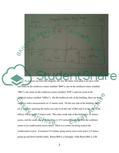
? Cymap: A Lab Report Word Count: 2,750 (11 pages) I. Introduction Before we get into introducing the building, let us talk a little bit about what this project is going to accomplish. First we have a program called Cymap, which is going to help create the design of a building in 3D. “In the field of building services (HVAC, etc.), there is, for example…a direct link with the software package CADlink/Cymap. This covers the areas of electrical, heating, ventilation and climate control installation.”1 Further, Cymap can be a very useful tool in getting to know what a building will look like before it is indeed built. “[Cymap was] designed to allow some small changes in the model and you can observe the effect.”2 In this case, we are not going to use Cymap, but pencil and paper, in order to show a drawing of the building. The drawing is not completely to scale. Even though it is a relatively rough, modest drawing, still one can see how the usage of metres of the room is being achieved, and a bit of math was done in order to deem how much space was left for other parts of the building to be constructed. Here what we will be showing to you, the reader, in our subsequent sections, is: the Building Definition; the Project Wizard; the Lighting Design; the Wiring Design; and finally a conclusion which will wrap up our discussion and thus conclude the lab report. Thus, the drawing is shown in Part II, entitled “Building Definition,” which we shall view next. II. Building Definition As you can see from this diagram, the way the basic room plan is set up is with: one room on the northwest corner (entitled “B60”); one on the northeast corner (entitled “B62”); one room on the southwest corner (entitled “S/W”); and one room in the southeast corner (entitled “Office”). On the northwest side of the building, there are three windows with a measurement of 1.5 metres each. On the east side of the building, there are 6 windows spanning the entire east side (4 on the side of B62 and 2 on the side of the office), which span 1.5 metres each. The entire north side of the building is 24 metres across, and the south side of the building is 15.5 metres long going from the southeast corner to its southwestern-most corner. There is a corner not being used in the southwestern corner. It measures 8.5 metres going across (east-west) and is 2.5 metres going up and down (north-south). Room B60 is a rectangle, while Room B62 is a bit oddly-shaped. There is a space between the office and the wall of the S/W room of about 6 metres across and 3.5 metres up and down. There are (what can only be assumed to be) marks meaning doorways, in 4 areas of the building. The S/W room has no doorway out except through the backway. Similarly, Rooms B60, B62, and the Office only have one doorway out apiece. Both B60 and B62 have doorways at the back, while the Office doorway is on the side and leads to Room B62 where the fourth doorway is at the back of the building. This could prove to be logistically difficult if one needed to get into or out of any of the rooms but the one doorway in each room were blocked. This would most definitely be a fire hazard. III. Project Wizard Since the building floor plan has been designed, now the process of services design can begin. The Cymap project is going to be defined. Next, the different aspects (stages IV through VI) can be designed in their proper sequence. For our purposes, we are going to develop these stages independently, one after another. However, the same sequence will be followed. On small tasks, only one service might be needed. It is assumed that this project will use the floor plan as given, and one or more types of services. This is contained within the entirety of this single project—which can then be linked to the floor plan in Cymap. In order to start a new project, I went to File, and then clicked on “New” to open the “New Project Wizard.” This helped set up my floor plan, and helped define the geometry and profiles of the rooms in the project and provided me with access to the chosen services, basically, Lighting, Electrics, and Wiring—which are the next crux of the project. After I clicked “Next,” I assumed that a .DXF file was created, and I selected “All floor plans in one DXF file.” Then I clicked “Next.” I saved and named the project as a .CYC file, which is the file name for Cymap. I also added teh name “Abdullah,” as that is my name and I decided to use it as a reference for the project to which I could refer later if there were any mistake in trying to search on my computer where the .CYC file was located. I set the floor, ceiling, and void measurements, accepting all the defaults. I pressed “Next. Then, I browsed for and selected the DXF file of the floor plan, again clicking “Next.” I accepted the default orientation. I clicked “Next,” and then clicked “Finish” to accept what I had created so far. Next, I accepted the default “Standard Elements,” as well as accepted the “Template Profile.” When I was prometed to define the rooms, I said “yes.” I then gave the first room its name, then clicked next—following all the on-screen instructions on how to define the room and shape and select its boundaries. I did this for all of the three other rooms in the floor plan, and then pressed Cancel. Then I was able to move to the required service. I wante to re-open an existing project, so I started Cymap and then selected the appropriate directory. I opened the .CYC file and selected my project name which I was going to work on. The project name appeared on the top bar of the Cymap window and showed me the main menu, giving access to the necessary services. Access was now possible to Wiring, Lighting, and Electrics through clicking on “Electrical.” In general, one can move from one service to another by clicking on File and then “Move to…” Alternatively, one can navigate back from a service to the main menu by going to File and then “Exit,” or by closing the window of that particular service. IV. Lighting Design The lighting design ensures that the type and number of fittings are suitable to provide appropriate lighting levels to the rooms. First we will detail the design of the laboratory B60, and then the other rooms will be designed in the same manner. In order to work on room B60 first, I opened the project on Cymap and then selected Lighting. In order to work on new lighting, I went to File and then to “New” and named the project “B60 Lighting.” The General Information dialogue box appeared and then I completed the various tabs, and used the feature for a Single Room only. I defined the light fittings first. I selected the required manufacturer’s light-fitting database and defined the lighting and fitting details for the project. Where data wasn’t given, I just used the default data or tried to amend it as best as I could to suit the particular needs of the project. For the Fitting DB file—I selected Philips Lighting UK 2005. For the Usage/Environment tabs, I selected 0.10 p/kWh and Latitude 55N. Next, the Settings for the Template Profile dialogue box appeared. I used 500 lux on the working plane. I used a Working plane height of 0.8 m, and entered 750 hours on. For the tube colour, I selected Polylux840—later on I tried different variations of colour to see how the results differed. I also used a Reflectance 70/50, the typical industrial reflectances for the ceiling and walls, respectively. I decided to skip external (floodlighting) lighting, because this also requires a .DXF floor plan, and I didn’t want to get too caught up in extraneous details on this project. I just wanted to be able to have the rooms equipped for the basic details. When the Fitting Details dialogue box appeared, I selected “Manufacturer All,” and then the 4Mx091/258 2xtl – D58/830 Hf fitting. I looked at the website http://www.lighting.philips.com. The height of the fitting from the ceiling was entered for fittings which are to be suspended from the ceiling, which I made to be 0.5 m. I then added the light fittings using the room index. I viewed the results. If any changes were needed at this point, I made them, and then I decided to Display Options so I could see various views of the choices I had input into the program. V. Electrics (Lighting and Small Power) Generally, all of the electrical design that was used in this program was in keeping with international requirements. “Electrical design packages including conformance check with the requirements of IEE 16th Edition wiring regulations, Lighting systems design and electrical CAD.”3 In order to go to the electrics part of the building design, I selected File, then Move To, and then “Electrics.” I determined the areas to be served by each distribution board. For each area in turn, I selected Insert, and then Board, and added a switchboard for each room. I chose TP&N and added a number of ways (10, because I was unsure) how these could be changed later if required. I selected Insert and then went to Symbol, placing and positioning the various items in the room, i.e. sockets, cooker, stationary items, and light switches (for example). I right-clicked to change orientation of items, and used ESC (the Escape key) to quit placing. Then I chose Insert and then Switching, in order to assign load equipment to each way. I clicked on the board and then selected a way and phase, and then clicked OK. I clicked once on the board and then on each socket or set of light fittings and their associated switches to be added to the way. I double-clicked the last item to finish selection. For the lighting portion this was the switch. I pressed the Escape key to finish with the board. I only used a max of 8 double sockets for the project. The maximum lighting circuit currents I chose were 4 or 6A, to be safe. I then added larger equipment (stationary equip) and connected this in a similar manner. For a value of current I entered 30 A to be safe. At certain points in the simulation I used the Redraw function to make the diagram look nicer. I selected Display and went to Unconnected to highlight any unconnected items in purple. I chose Insert and then Cable Supports to add conduit, trunking, perforated trays, and a ladder track. I double-clicked on the last item to be connected to finish. I added cable lengths to the switchboard. For each circuit, I clicked on the switchboard, then followed the support structure route, clicking on each item in the circuit. I made the cable runs 100 m or less in length as not to stretch the cables to the max. On completion of each circuit, I selected Insert, and then Switching. Then I clicked the Show Cable Length option to view the length of the cable. At various points I clicked Cancel to return to insertion of more cable lengths. In order to save time, I calculated the lengths to a common point and pressed record, then connected each item to the common point, the length of the common point having been added to each cable run. I reviewed all cable lengths by repeating the selection of Insert and then went to Switching, and then clicked the Show Cable Length option. I repeated these steps for each room, and finally saved the project. VI. Wiring Design The previous stages of this project determined the loads, not including the number of ways on each switchboard, however, it doesn’t mean that the cable sizes were defined, nor were the interconnections between the board and the site main incomer. The wiring program was used to define the inter-connectability of all the rooms, allowing the generation of a list of components required to complete the necessary installations. From the menu, I selected “Electrical,” then selected Wiring 17th Edition, then opening the new Wiring file which I used to incorporate the main incomer and the switchboard. I selected the IEE BS7671 Standard, because obviously the Wiring 16th Edition was old (the source used for this paper was actually too old, so I made sure to choose the 17th Edition as demanded by the UK Wiring Regulations from 2008). When the General Information dialogue box appeared, in the General tab, I added my own name, Abdullah, as a reference name for the file and selected BS7671_17th + ERA 2008.DBY as the cable database. I also selected the CPD database. I included a supply transformer. I used a 5% impedance and selected an earth type I thought was appropriate (I used TN-C since that was recommended). I used the Calculate button to determine the fault levels. In the Sub-Mains tab, I specified the CPD type as BS88 Fuse, set the max volts drop as 2.5%, and the cable type as Cu XLPE A (with Armour as CPC)> I ticked Use Spare VD (volt drop). In the Final Circuits tab, I specified the CPD type as BS88 Fuse, setting the max VD as 1.5%, and the cable type as CU PVC Si, which is a separate CPC in non-continuous conduit. Then I ticked Use Spare VD. I then accepted any other known defaults in the program. I selected File, then Import, then selected the previously-saved scheme CYC file. I highlighted each switchboard in turn, clicking Select All, and then Import. These now appeared in the wiring diagram, where I moved them on-screen to suit. These Final Boards were ready to have RCD’s added to them when I was prometed to add them onto the circuits. I went to Insert, then to Main Board. I inserted the number of circuits required, including extra circuits for future development. I gave the Board a name, a rating (250 A worked fine), as required for the installation. I pressed Escape to stop placing any further Main Boards. I connected the cables between the supply, main board, and final boards. To do this, I went to Insert, then Cables, then clicked on the Main Board and then on the 1st Final Board. I inserted the cable length, type, and installation method in the dialogue box. I selected the CPD type as a BS88 Fuse and selected OK, repeating this step for any subsequent boards I encountered. I then connected the cable between the supply and the Main Board. I pressed Escape to finish. I saved the file as a Wiring file, .CYW. I then selected Display, and then Calculate All, which calculated the cable sizes required and showed the sizes for the main cables on the screen. I clicked Display, then Options, allowing me to select which information was shown onscreen. I then clicked Display, and then Schedules to see the cable schedule for the main cables. I also checked Display and then Summary to see the loads adn voltage props for each line of the supply. VII. Conclusion In this lab report, I have shown what was designed in Cymap with a hand- drawn drawing what I actually did when I was going step-by-step through the automated computer program, which generated several of the necessary defaults. For most places where I was asked to enter figures, I usually went with what was the minimum limit because I didn’t want to stress out the system or use all of my maximum limits with various figures—such as the cable lengths. Many of the figures were variable, but Cymap definitely made the process easier. With Cymap, we were able to go through each step of the building process, in effect designing the following elements, which include: the Building Definition; the Project Wizard; the Lighting Design; the Wiring Design; and finally this conclusion, which wraps up our entire aforementioned discussion and thus concludes this lab report. WORKS CITED Maier, Pat, et al. Integrating Technology in Learning & Teaching: A Practical Guide for Educators. US: Psychology Press, 2000. Pp. 57. Martens, Bob, et al. ArchiCAD: Best Practice: The Virtual Building TM Revealed. US: Springer, 2004. Pp. 282. Sun, Ming, et al. Understanding I.T. In Construction. US: Taylor & Francis, 2004. Pp. 85. Read More
Tags
Cite this document
  • APA
  • MLA
  • CHICAGO
(“Cymap Coursework Example | Topics and Well Written Essays - 2750 words”, n.d.)
Retrieved de https://studentshare.org/engineering-and-construction/1392199-cymap
(Cymap Coursework Example | Topics and Well Written Essays - 2750 Words)
https://studentshare.org/engineering-and-construction/1392199-cymap.
“Cymap Coursework Example | Topics and Well Written Essays - 2750 Words”, n.d. https://studentshare.org/engineering-and-construction/1392199-cymap.
  • Cited: 0 times

CHECK THESE SAMPLES OF Cymap for Showing a Drawing of the Building

Details of structural members in concrete and steel buildings

Advanced technology through Computer Aided Design has improved designing work with building codes controlling the steel industry.... Strength design method was adopted by the International building Code (IBC) in its 1956 edition.... Concrete and steel have been used for many years in construction industry....
10 Pages (2500 words) Essay

Ethics and Professional Practice in Architecture

The essay "Ethics and Professional Practice in Architecture" critically analyzes the major issues of ethics and professional practice in the field of architecture.... A professional is a person who is an expert and has specialized knowledge in a particular field of which one is practicing.... ... ...
9 Pages (2250 words) Essay

Green Building

Moreover, research has shown that having chemicals sprayed over the grass eventually leads to the clay soil beneath the foundation of the building stronger and can assist during the rainy season (Vasil, 2009, 77).... the building is located in a busy location with a lot of traffic.... It is thus important to understand that the cars passing by the building do not spend a lot of time at the location because the ground is rather weak.... It is a requirement that the building uses rather tough tiles and the most recommended is the ceramic tiles....
9 Pages (2250 words) Research Paper

Importance of the Building and Construction Industry

The paper "Importance of the building and Construction Industry" describes that the steel may suffer from creep rendering it to sag or the bolts used in joining the structural members become loose.... Since the length of the building is 250000 mm, then, the number of pillars along one wall is equal to 125.... The structural designer must work according to the building standardization codes....
5 Pages (1250 words) Essay

From Urban Sprawl to Compact City

Due to a fragmentation of interests in the building processes, ambiguity regarding the definition of sustainable buildings and the absence of easily recognizable business cases, there can be difficulty faced in creating sustainable buildings.... The paper 'From Urban Sprawl to Compact City' is on architecture management, practice, and law....
28 Pages (7000 words) Dissertation

Building Conservation

This is important given the existing contrast between the image of the building at the time it was constructed and in the modern era.... The design also considered aspects like the capacity of the building occupants and the type of spaces required for its full functionalism.... This was basically meant to reduce the weight of the building along with its height.... The same goal is achieved through a decrease in the base size of the building along with its height....
14 Pages (3500 words) Term Paper

Geothermal Energy in Iceland

This research begins with the statement that looking at the current rate by which fossil fuel is being used reveals a probability of energy crises in the future.... Many countries have thus engaged inputs from energy specialists top carry out thorough researches concerning the looming energy crises....
5 Pages (1250 words) Coursework

The World Famous Attractions

the building was constructed by Étienne-Louis Boullée, who was the lead architect in the establishment of the Cenotaph in 1784.... the building was built in honor of England's scientist, Isaac Newton.... the building possesses an iron and glass study room, which is described as magisterial and the representation of a modern library.... Its planning and building were conducted by the construction company owned by Engineer Gustave Eiffel, and after completion, the tower was named after him....
7 Pages (1750 words) Essay
sponsored ads
We use cookies to create the best experience for you. Keep on browsing if you are OK with that, or find out how to manage cookies.
Contact Us