StudentShare
Contact Us
Sign In / Sign Up for FREE
Search
Go to advanced search...
Free

Intelligent Micromouse - Essay Example

Cite this document
Summary
The paper "Intelligent Micromouse" highlights that the sensor cable of Intelligent Micromouse should be about 30cm in maximum length. This sensor is a common component of choice for most projects in which accurate measurements of distance are required…
Download full paper File format: .doc, available for editing
GRAB THE BEST PAPER96.9% of users find it useful
Intelligent Micromouse
Read Text Preview

Extract of sample "Intelligent Micromouse"

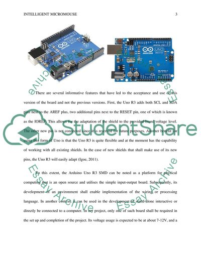
Intelligent Micromouse Arduino Uno- R3 SMD An Ardiuno Uno-R3 SMD refers to a microcontroller board that is majorly based on theATmega16U2 instead of the previous versions such as the 8U2 that is commonly found on the Uno of in the case of previous generations that had FTDI. The use of this new version of the mega (ATmega16U2) benefits the board in the sense that it allows for the quicker rate of transfer and provision of extended memory (Ashby, 2011). Basically, this board contains everything that is required for the support of a microcontroller. Its functionality is also quite simple as all that is a prerequisite is a link to a computer through a USB cable or it is powered using an AC-to-DC battery or adapter. This board is the new version of the Arduino Uno and when used in the operation systems such as Linux and Mac, there are no drivers that are needed. However, for Windows, the inf file is required and incorporated into the Arduino IDE. Subsequently, this new form of Arduino Uno R3 has the capability to have the Uno feature as a mouse, joystick or keyboard (Margolis, 2013). A diagrammatic image of the Arduino Uno R3 SMD is as shown below. Figure 1: Arduino Uno R3 SMD boards There are several informative features that have led to the acceptance and use of this version of the board and not the previous versions. First, the Uno R3 adds both SCL and SDA pins next to the AREF plus, two additional pins next to the RESET pin, one of which is known as the IOREF. This allows for the adaptation of the shield to the provided board voltage level. The other new pin is not connected since it is reserved for future purposes. Another benefit for using this form of Uno is that the Uno R3 is quite flexible and at the moment has the capability of working with all existing shields. In the case of new shields that shall make use of its new pins, the Uno R3 will easily adapt (Igoe, 2011). To this extent, the Arduino Uno R3 SMD can be noted as a platform for physical computing that is an open source and utilises the simple input-output board. Subsequently, its development of an environment shall enable implementation of the wiring or processing language. In another context, it can be used in the development of stand-alone interactive or directly be connected to a computer. In my project, only one of such board shall be required in the set up and completion of the project. Its voltage usage is expected to be at about 7-12V, and a clock speed of 16 MHz. The item code for this component as shall be used in the project is DEV-11224. 2. Mini Metal Gearmotor 100:1(+ROB-08899 Wheel 42x19mm) This is a gear motor that has a plastic custom designed wheel from Pololu. The intended voltage usage for the gearmotors shall be 6 V as the nominal voltage although there are instances when these gearmotors shall be used when running at lower or slightly higher voltages than this nominal value. However, the effect of this is that the higher voltages might have a negative impact on the life of the motor. The gear motor has a ROB of 088912 and a 7mm D-shaped metal shaft that has similar physical features as those of a Pololu wheel 42x19mm (Karvinen & Karvinen, 2011). The gear motor has two mounting holes that both have threads for M2 screws. The features of this gear motor are 100:1 gear ratio, 140rpm @6V, 60mA @6V and a torque of 26 oz inches @6V. Other standard operating conditions for the gear motor include an operational temperature of between -100 C to 600C and a counter clockwise direction of rotation, especially when the motor output is viewed from the side together with a positive voltage that has been applied to its positive terminal (Bräunl, 2008). As a mechanical characteristic, the end play for the gear motor should be less than or equal to 0.4mm. Other measuring conditions for the gear motor are an environmental humidity of 65% RH and an environmental temperature of 210C. In the project, 2 of these gearmotors will be used considering that they also sold in pairs. Subsequently, while carrying out the project, the motor will be held in a horizontal position with the shaft. Diagrammatic representations of this motor are as shown below. The item code for this component as shall be used in the project is ROB-08912. Figure 2: Mini Metal Gear motor 100:1(+ROB-08899 Wheel 42x19mm) Source: http://www.allthingsnow.com/day/tech/shared/5551807/Mini-Metal-Gearmotor-100-1-SparkFun-Electronics 3. Wheel 42x19mm The measurement of the rubber tire’s diameter approximates at about 42 mm and the ROB is 08899. The deigning of this diameter is to enable the fitting of all output shafts in the mini metal gearmotors and other types of gearmotors such as solarbotics and micro metal gearmotors. The teeth of the gear motor’s hub allows for the use of a reflectance sensor in the encoding of necessary feedback (Barrett, 2012). The ruggedness of this type of wheel as designed is to allow for the secure fitting of the wheel into the output shafts of the mini metal gearmotors. These wheels can also efficiently be fitted with the Solabotics metal gear motors given that such motors are shorter hence; will definitely fit in the reverse side of the wheel when mounted at the point where the fit is tighter. An example of such a wheel is as shown in the figure below. Figure 3: Mini Metal Gear motor Source: https://www.sparkfun.com/products/8899 In this project, the use of this wheel in the mounting of the gearmotors takes into consideration the fact that the gearmotors are to be mounted onto the hub’s side, in line with the protruding teeth. This will allow for easy sliding of the output shaft into the socket in the first round. The item code for this component as shall be used in the project is ROB-08899. 4. Motor Driver 1A Dual TB6612FNG This is a motor driver that is usually used in the driving and control of the DC motors at a constant level of current, usually 1.2A on the lowest end and 3.2A on the peak. Consequently, the motor driver can control a one bipolar stepper motor, but, with a recommended voltage rate of between 4.5 – 13.5V for the motor. Its ability to allow for the current peak of 3 A in a single channel makes it to become a great motor driver for usage in the low power motors. Using, two DC motors, the TB6612FNG motor driver uses two input signals (IN1 and IN2) to control the motor when it is in its any of the four functional modes of CCW, CW, short brake or stop. The two DC motor outputs can be controlled separately by controlling the speed of each of the motors through a PMW input signal that has a maximum frequency capacity of 100 kHz (Scherz, 2013). The reason for the choice in this type of motor for the project is because of its exceptional value, small size and the requirement of little effort in order to set it into the working mode. The TB6612FNG is an H-bridge driver that has its end result capable of turning a connected motor in all directions thus, allowing for the building of an agile robot or device that is driven by the two motors (Habib & Davim, 2013). The significant features of this component as strategically identified in this project are: Standby control for saving power. An output rate of current of 1.2A on average and 3.2 A at peak. A power supply voltage that reaches a maximum of 15V. Four control modes of CW, CCW, short brake and stop. Capacitors on both lines that are used for filtering. A built-in thermal circuit for shutdown. Expected dimensions of 08 x 0.8”. A diagrammatic representation of this motor driver is as shown in the figure below. Figure 4: Motor Driver 1A Dual TB6612FNG Source: http://proto-pic.co.uk/motor-driver-1a-dual-tb6612fng/ In most instances, the breakout boards for this motor driver come without pins; hence, one is required to solder their own in making the connections for the various terminals. Only one component shall be required for the project and the identifiable code for the component is ROB-09457. 5. Encoder for Pololu Wheel 42x19mm Wheel 42x19mm is functional when it is combined or attached to an encoder. This encoder (quadrature encoder board) is usually premeditated to function with the metal gearmotors by acting as a holder for the two infrared reflectance sensors that are located inside the 42x19mm wheel hub. The encoder shall also be used to measure the association of the teeth positioned lengthwise the rim of the wheel. This encoder also has an extended bracket that aids it to calculate the speed of rotation of the wheel and direction that the wheel turns. The combination of the wheel and the encoder are intended to enable the achievement of a differential drive in building of a robot. Given that wheel 42x19mm has the twelve teeth, the encoder shall enable it to achieve a resolution of 48 counts in each revolution thus, directly correspond to a 3mm linear resolution of the wheel. A complete set of the wheel and the encoder comprises of: Four mounting screws and nuts. Two encoders for the wheel 42x19mm. A pair of micro metal gear motor bracket extended. A pair of Pololu wheel 42x19mm. Diagrammatic representations of this component as combined with the wheel are as shown in the figure below. Figure Source: http://www.pololu.com/product/1217 The definitive features of this encoder are that its operating voltage ranges between 4.5V to 5.5V, although it can be modified for lower voltages. It also has two digital outputs, which when combined result in the quadrature. Its consumption of current at 5V is equivalent of 14 mA and has a single revolution comprising of 48 counts. Subsequently, its small size enables it to fit perfectly between the chassis and the motor. This encoder is good in that it can be modified to allow for a 3.3 V operation up from a 5.0 V by the reduction of its IR emitter of the current limiting resistance and a calibration of its phototransistors. In this project, the component shall be coded as PPPOL1217 and shall aid in the determination of the rotational and directional speed of the gear motor wheel. 6. IR Distance Adapter This adapter is usually designed with the goal of interfacing it with the sharp IR distance sensors into an analog input on a Phidget interface board (International Conference on Machine Automation, Shirase & Aoyagi, 2010). Diagrammatically, this adapter can be as represented in the figure below. Figure 6: IR Distance Adapter Source: http://www.phidgets.com/products.php?product_id=1101 The importance of this adapter is that it allows for the connection to the distance adapter board through the use of interface cables. However, compatibility is essential and the adapter should be compatible with the other components. The adapter’s main function is the regulation of the power requirement for the project’s connected sensors. Its voltage production ranges from 0 to 2.5V which is interpreted in the form that the sensor has a value of approximately 500. In using this adapter, the distance range for the product that is being measured should be within the sensor’s range distance (Blum, 2013). This is because an object lying outside of the valid range will result in unwanted results which should then be discarded. The definitive features of this adapter include an analog interface, a module cable of 60cm length, and a sensor cable of 30cm length. Subsequently, its input voltage is usually between 4.8V and 5.3V with a power adapter board that utilises 3 mA. In this project, this component shall be coded as 1101_0. 7. Sharp Distance Sensor (4-30cm) As noted above, the sensor cable should be about 30cm in maximum length. This sensor is a common component of choice for most projects in which accurate measurements of distance are required. This is because it more economical than the range finders and has the capability of providing better performance than the IR alternatives. Interfacing for the microcontrollers for this sensor are quite straightforward thus, allowing for the connection between the analog and digital converter in a single phase that can then be used to enhance the measurement of the distances. The foremost features of this device are that its operating voltage ranges between 4.5V to 5.5 V and has a current consumption of averagely 33 mA. Its rage of measuring distance is between 4cm to 30cm and has an output type of analog voltage. At 4cm the sensor has the capability of producing an analog output of 3.1V, while at 30cm; it produces an output voltage of 0.3V. The sensor also has the capability of determining the differential in the range of distance based on the output voltage of about 2.3V. Its response time is approximately 38 ms with a variance of +/- 10ms. There is a linear relationship existing between the output voltage of the sensor and its inverse measured distance depending on the usable range of the sensor. The most common version of this sensor is the GP2D120 that uses a 3-pin JST connector and the cables which should first be soldered to the sensor. Based on the typical values that can be determined form the sensor, the distance can be calculated through the translation of the sensor values into distance by following the following formula. However, this formula is usually applicable for sensors that have values ranging between 80 to 530. Distance (cm) = 2076 ÷ (Sensor Value - 11) Using this formula, it can be possible to calculate the distance between objects that offer very narrow edges, for instance, a wall with a sharp angle. The illustration below displays the association between the Sharp Distance Sensor to the IR Distance Adapter through the interface cable 30cm long. It also connects to the motor driver. Figure 7: Connection of Sharp Distance Sensor to the IR Distance Adapter Source: http://www.phidgets.com/products.php?product_id=3520 In this project, this component is coded as 3520_0. Figure 8 below show other images of the sensor. Figure 8: Sharp Distance Sensors images Source: http://www.pololu.com/product/1136 References Ashby, D. (2011). Electrical Engineering 101: Everything You Should Have Learned in School ... but Probably Didnt. Burlington: Elsevier Science. Barrett, S. F. (2012). Arduino microcontroller: Processing for everyone!. S.l.: Morgan & Claypool. Blum, J. (2013). Exploring Arduino: Tools and techniques for engineering wizardry. Hoboken: Wiley. Bräunl, T. (2008). Embedded robotics: Mobile robot design and applications with embedded systems. Berlin: Springer. Habib, M. K., & Davim, J. P. (2013). Interdisciplinary mechatronics: Engineering science and research development. London: ISTE. Igoe, T. (2011). Making things talk: [Practical methods for connecting physical objects]. Sebastopol, CA: Maker Media. International Conference on Machine Automation, Shirase, K., & Aoyagi, S. (2010). Service robotics and mechatronics: Selected papers of the International Conference on Machine Automation : ICMA2008. London: Springer Verlag. Karvinen, K., & Karvinen, T. (2011). Make Arduino bots and gadgets: Learning by discovery. Sebastopol, Calif: OReilly. Margolis, M. (2013). Make an Arduino-controlled robot. Sebastopol, Calif: OReilly. Scherz, P. (2013). Practical electronics for inventors. Maidenhead: McGraw-Hill. Read More
Tags
Cite this document
  • APA
  • MLA
  • CHICAGO
(Intelligent Micromouse Essay Example | Topics and Well Written Essays - 2250 words, n.d.)
Intelligent Micromouse Essay Example | Topics and Well Written Essays - 2250 words. https://studentshare.org/design-technology/1825215-intelligent-micromouse
(Intelligent Micromouse Essay Example | Topics and Well Written Essays - 2250 Words)
Intelligent Micromouse Essay Example | Topics and Well Written Essays - 2250 Words. https://studentshare.org/design-technology/1825215-intelligent-micromouse.
“Intelligent Micromouse Essay Example | Topics and Well Written Essays - 2250 Words”. https://studentshare.org/design-technology/1825215-intelligent-micromouse.
  • Cited: 0 times

CHECK THESE SAMPLES OF Intelligent Micromouse

Undertaking intelligent intermittent auscultation

Undertaking intelligent intermittent auscultation It ensures that there is no risk to the child in utero and that intra uterine fetal death does not occur undetected posing the risk of disseminated intra vascular coagulopathy to the pregnant mother.... The intelligent intermittent auscultation is more involving and demands both experience and a keen ear (Feinstein, 2012).... It is more superior to the intelligent intermittent (Hardling, 2012)....
3 Pages (750 words) Essay

Is intelligent design science

intelligent design is a new branch of knowledge originated in America recently which says that certain features of the universe and of living things are best explained by an intelligent cause, rather than a natural selection.... intelligent design...
4 Pages (1000 words) Essay

The Concept of Intelligence

A person attaining a low score in an IQ test does not show that he/she is less intelligent because they can be good at other things such as interpersonal communication (Sdorow & Rickabaugh, 2005).... The essay 'The Concept of Intelligence' presents the concept of intelligence testing which is something that evolved thousands of years ago....
1 Pages (250 words) Essay

Intelligence and Wisdom

The essay "Intelligence and Wisdom" states that few people would describe former New York governor as anything but an intelligent man.... Everyone would agree he was intelligent.... He went to the best schools and had a brilliant career.... He had a large vocabulary and knew a lot about law and politics....
1 Pages (250 words) Essay

What is Intelligence

We can measure the intelligence by means of various psychometric approaches encompassing intelligence test, where IQ or the intelligent quotient of the individual is calculated.... According to Sternberg, "human intelligence is the mental quality that consists of the abilities to learn from experience, adapt to new situations, understand and handle abstract concepts and use knowledge to manipulate ones environment....
1 Pages (250 words) Assignment

Report writing/ Intelligence and Wisdom

A university professor is an intelligent individual who has been studying for years and, as a result, holds a number of degrees.... As long as the reader is a medic and he or she will be assisting in further treatment of the patient, then the client's confidentiality cannot be jeopardized....
2 Pages (500 words) Research Paper

Tactical Intelligence Issues

Assessment of intelligent comes from the reliability of the information given.... The interpretation of information is critical to the S-2s, because giving information which has no objective misleads the agents.... Relating to Major Gerald… stafson, the decision to rescue the friend whose jet hand been brought down, was due to objectivity that he was the only one would save the Major before the jet went down....
2 Pages (500 words) Essay

Intelligence Research Methods

lthough both scholarly and intelligent research methods might seek to determine whether data is reliable and authoritative, the scholarly researchers have not embraced the notion of going out and searching for data sources as the intelligence community does with security in mind....
1 Pages (250 words) Essay
sponsored ads
We use cookies to create the best experience for you. Keep on browsing if you are OK with that, or find out how to manage cookies.
Contact Us