StudentShare
Contact Us
Sign In / Sign Up for FREE
Search
Go to advanced search...
Free

Nose Cone for Open Wheel Climb Race Car - Lab Report Example

Cite this document
Summary
The paper "Nose Cone for Open Wheel Climb Race Car" discusses that the lift force and drag present in the baseline model was substituted by a downforce. Although the downforce on the nose was negligible, the downforce generated on the front wing is what mattered…
Download full paper File format: .doc, available for editing
GRAB THE BEST PAPER94% of users find it useful
Nose Cone for Open Wheel Climb Race Car
Read Text Preview

Extract of sample "Nose Cone for Open Wheel Climb Race Car"

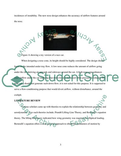
NEW NOSE CONE FOR OPEN WHEEL CLIMB RACE CAR al Affiliation) Key words: aerodynamics, nose cone, race car, front wing INTRODUCTION New technology has led to the evolution of open wheel climb race cars. In the past, open wheel climb race cars had front-mounted engines which had similar characteristics as hill climbing cars. The need to generate a clean flow of air along the car led to the sophistication of race car aerodynamics. The main objective was to streamline the car by designing a perfect nose cone; which minimizes the total drag. By developing rear-mounted engine race cars, thinner noses were developed. The nose cone is responsible for setting up airflow over the whole race car. This is very important for the car’s aerodynamic stability and performance. The nose cone covers a greater portion of the frontal area of the race car. It has a great impact on the downstream airflow to following parts; such as diffuser and side box. All parts of an open wheel race car require thorough assessment and their composition is dynamic. Areas that are thoroughly investigated include; nose and front wheel fairing, surface area, and tail plane adjustment. All these areas create engineering opportunities for innovation and advancement (Andersson, 2012). The nose cone aims at generating clean airflow so as to reduce turbulence. The design of the nose cone matters in terms of airflow that is dictated by whatever occurs at the nose. When the race car is running at a very high speed, some parts receive airflow in speeds of upto 100km/h. The actual airflow around the care cannot be accurately predicted at this state; therefore, the nose should be in constant communication with other parts to avoid any incidences of instability. The new nose design enhances the accuracy of airflow features around the nose. Figure A showing a toy version of a race car. When designing a nose cone, its height should be highly considered. The design should focus on the intended under tray flow. A low nose cone reduces the amount of airflow going under the car, deriving air upwards and sideways around the car. A high nose cone enhances mass airflow under the car implying that down force is increased while pressure is reduced. The nose cone should not generate such down flow; it is not suited for this purpose. It is supposed to serve a flow-conditioning purpose that would divert airflow, without disturbance, around the cockpit. LITERATURE REVIEW Various scholars came up with theories to explain the relationship between geometry and aerodynamics. Two such theories include; Prandtl Lifting-Line Theory, and Bernoulli’s equation theory. The lifting line theory indicated how wing geometry was required for elliptical loading. Bernoulli’s equation offers a more general approach to obtain the parameters of motion by applying the principle of conservation of energy. It states that; where friction is negligible, the sum of gravitational potential energy () and kinetic energy () is constant. Replacing mass () with static pressure (), we can rewrite the above statement as the Bernoulli’s equation:  We know that; kinetic energy + potential energy =constant In this case, since we are using computational fluid dynamics, the fluid of domain is gas; since the system utilizes computational fluid dynamics. This means that the gravitational force can be neglected. Therefore,  The above equation represents the communication presumption between statistic pressure and velocity. This communication can be indicated using a contracting and expanding pipe as shown below. A contracting and expanding pipe A change in the shape of geometry can cause a huge difference in static pressure; that is, at section 1 and section 2. The contracted part of the pipe changes the area where the fluid goes through. Velocity of the fluid increases in this part to guarantee the massive conservation. As velocity increases, static pressure reduces to ensure that the total pressure is able to keep the flow constant. With this basic theory, the generation of down force lift is well understood to enhance the advancement in designing the outer shape of the nose cone. The knowledge derived from this theory also affects the design of the inversed wing, which is valuable for nose cone design. Bernoulli’s equation implies that increasing velocity reduces pressure, therefore, reducing the lift on the lower surface of the nose cone. This statement can be illustrated as follows;  Generating down force BASELINE MODEL STUDY The baseline model is based on a lower nose configuration. There are strong relations between the nose and the front wing of a race car. The front wing impacts the flow features of other components besides having the ability to change the airflow structure around the nose cone. The baseline model study focuses on the flow behind the front wing. A proper nose is supposed to produce a down force with minimum drag forces. The performance of the nose cone is judged by observing the aerodynamic performance of the whole car instead of isolating the nose. From Bernoulli’s equation, it is evident that pressure and velocity contours have an effect on drag and lift hence they are taken to observe airflow around the nose. Figure B shows an image of a baseline model race car GEOMETRY OF THE BASELINE MODEL The baseline model has a convex upper surface and a concave lower surface as shown below. Figure C, baseline nose model (top view and side view) Velocity is increased when air flows along the upper surface. The lift force that is generated is not expected in the design. Nose cone design aims at lowering velocity to ensure that it is equally distributed along the chassis to acquire a down force. BASELINE ANALYSIS Figure D, velocity distribution over baseline nose (side view) In Figure D above, the baseline generates an expected flow. Airflow stagnates at the front wing, due to the small surface area. On the upper surface, airflow increases steadily and reaches a point of free stream velocity. The boundary layer thickness is reduced up to the point where the curved part of the nose shifts to the flat part. A positive pressure gradient is noted at the lower part, which is responsible for airflow undertray conditioning. High airflow velocity between the nosecone and the front wing results in the generation of lift along the lower surface. A convex lower surface would be recommended in the design for the new nosecone to reduce the lift. Figure D, pressure coefficient distribution over baseline nose (side view) The figure above indicates the coefficient that indicates pressure over the symmetry plane. The extremely red area at the tip of the nose represents a high pressure area; 1.0149. At this point, airflow velocity is significantly reduced. As in the previous case, airflow velocity increases sharply as it flows between the lower surface of the nose cone and the lower front wing. Increased velocity reduces the pressure at the point of stagnation. This proves the Bernoulli’s relationship between pressure and velocity indicating its importance in the design of a new nose cone. Figure E, velocity vector over baseline nose (side view) The velocity vector diagram above indicates how velocity behaves between the boundary layer area and the gap. At the boundary layer area, velocity is very low since pressure is very high, hence the low scale of 17.270m/s. As airflow proceeds further into the gap, velocity is accelerated as pressure is significantly reduced. CONCLUSION The above study not only proves the Bernoulli’s equation; showing the relationship between pressure and velocity, it also shows the necessary advancements required for the nose cone to reduce lift force while promoting down force. A lower baseline tends to form a ‘tunnel’ with the ground. According to Bernoulli’s Effect, a high pressure area at the front of the nose forces airflow to be directed into the ‘tunnel.’ As airflow moves further into the ‘tunnel,’ pressure is reduced as velocity is accelerated. This would create negative pressure meaning that more airflow will move into this region. Increased airflow would tend to create a lift force making the race car extremely unstable. In designing a new nose cone, the length of the nose should be considered to ensure that enough down force would be generated. In the baseline model, the length of the nose combined with the front wing reduced the down force of the front wing. A balanced design for a new nose cone is required to guarantee the down force of the new wing. A concave upper surface would minimize drag over the surface of the nose whereas a convex lower surface of the nose would be combined with the lower front wing for a high nose design (Schwartz, 2010). A design for the new nose cone should first be tested in the race car to establish its feasibility. Combining a new design with the front wing would have a significant effect on pressure, which would dictate the generation of down force or lift force. From this model, it is observed that air flow is transferred from the sides to the lower surface. This explains the changes in velocity. NEW NOSE ANALYSIS Figure F, new design New design objective From the baseline model, a new nose cone was designed with the same knowledge but applying advanced technology with assistance from Bernoulli Effect. The new design would serve the following objectives: To ensure that instability in race cars is dealt with; To prove that Bernoulli Effect is responsible for down force; To increase the height of the nose cone for an efficient airflow structure; and To increase the length of the nose cone so as to generate a greater down force NEW NOSE MODEL GEOMETRY Figure G, new nose model (top view and side view) In this design, the height of the nose cone is significantly increased. It is evident from this increment that the new height had positive effects on the race car. Increasing the height means that the distance between the lower surface of the nose cone and the upper surface of the lower front wing is increased. From figure G, it is visible that the thickness of the frontal nosecone is lesser than that of the baseline model. By comparing figure C with figure G, it is evident that the length of the nose cone has increased. This increment in length is due to an extension of the double front wing by a small nose. The connection of the small nose (bridge) was made possible by lowering the front of the nose. This explains the shape of the nose cone from the side view. The lower surface has also been slanted unlike in the baseline model whereby it was flat. The lower surface connects with the splitter underbody at the interior end of the slant. At the cockpit interface, the splitter has the same width as that of the nose cone. NEW NOSE ANALYSIS Figure H, velocity distribution over new nose (side view) As the figure above indicates, velocity on the lower surface of the nose is not increased. The blue region indicates the lowest velocity of air flow. Acceleration occurs on the upper surface of the nose; indicated by the different shades of green. As compared to the baseline model, airflow velocity does not reach its maximum due to the large surface area at the upper surface. Airflow is not restricted as compared to the ‘tunnel’ in the previous model. Figure I, pressure coefficient distribution over new nose (side view) As the figure indicates, an increase in height would force airflow into the region between the lower surface of the nose and the lower surface of the upper front wing. Positive pressure is generated in the tunnel up to 1.0250. This positive pressure influences the formation of a suction area above the nose cone. This suction results in increased airflow on the upper surface of the nose generating a down force on the front wing while increasing the lift on the nose. Figure J, velocity vector over new nose (side view) Velocity on the lower surface of the nose does not increase due to the high pressure in the ‘tunnel.’ This is indicated by the blue shade. There is lower velocity of airflow in the tunnel whereas velocity is accelerated on the upper surface of the nose. Figure K, streamlines around the car The smooth streamlines, indicated by the green waves, are attributable to the increased height of the nose. They represent the attached flow that passes through the splitter underbody. This is beneficial towards the stability of the car. Increased airflow in the tunnel would generate a higher down force on the front wing as compared to the baseline model; whereby a lift force was generated. Additionally, increasing the height of the nose would enhance the splitter to direct airflow towards the diffuser. The down force on the nose is neglected, as more down force is generated on the front wing with increasing airflow into the tunnel. CONCLUSION From the above analysis, it was evident that improving the nose cone design led to a significant reduction on the lift on the nose. The lift force and drag present in the baseline model was substituted by a down force. Although the down force on the nose was negligible, the down force generated on the front wing is what mattered. The negative pressure generated on the suction area, upper surface of the nose, ensured that a down force was maintained throughout. Bernoulli Effect was proved in this new design. High pressure in the tunnel meant that velocity was greatly reduced. Smooth stream lines were generated in the tunnel enhancing the efficiency of the splitter. Increasing the length and height of the nose enhanced the stability of the race car. Mass airflow transfer from under the nose cone and lower velocity at the centre plane reduced the overall lift generated by the nose cone. . Increased airflow in the tunnel would generate a higher down force on the front wing as compared to the baseline model; whereby a lift force was generated. Additionally, increasing the height of the nose would enhance the splitter to direct airflow towards the diffuser. The down force on the nose is neglected, as more down force is generated on the front wing with increasing airflow into the tunnel As indicated in figure G, the upper surface of the nose is convex while the lower surface is concave. This ensured smooth airflow by creating an acceleration area on the upper surface of the nose and a high pressure area on the lower surface. According to Bernoulli Effect, velocity was greatly reduced in the high pressure area, ensuring that smooth streamlines were generated. This created room for more airflow in the tunnel hence the splitter was able to maintain the down force as generated (Shuler, 2012). REFERENCES Andersson, B. 2012. Computational fluid dynamics for engineers. Cambridge: Cambridge University Press. Schwartz, H. E. 2010. The science of a race car: reactions in action. Mankato, Minn.: Capstone Press. Shuler, M. 2012. Rocketry Science. New Delhi: World Technologies. Read More
Tags
Cite this document
  • APA
  • MLA
  • CHICAGO
(Design and analysis (aerodynamics) of the new nose for open wheel Lab Report, n.d.)
Design and analysis (aerodynamics) of the new nose for open wheel Lab Report. https://studentshare.org/design-technology/1821566-design-and-analysis-aerodynamics-of-the-new-nose-for-open-wheel-climb-race-car-in-by-using-cfd-computational-fluid-dynamics-2500-words
(Design and Analysis (aerodynamics) of the New Nose for Open Wheel Lab Report)
Design and Analysis (aerodynamics) of the New Nose for Open Wheel Lab Report. https://studentshare.org/design-technology/1821566-design-and-analysis-aerodynamics-of-the-new-nose-for-open-wheel-climb-race-car-in-by-using-cfd-computational-fluid-dynamics-2500-words.
“Design and Analysis (aerodynamics) of the New Nose for Open Wheel Lab Report”. https://studentshare.org/design-technology/1821566-design-and-analysis-aerodynamics-of-the-new-nose-for-open-wheel-climb-race-car-in-by-using-cfd-computational-fluid-dynamics-2500-words.
  • Cited: 0 times

CHECK THESE SAMPLES OF Nose Cone for Open Wheel Climb Race Car

Contrasting Frosts the Road Not Taken and a Worn Out Path by Wendy

Symbolism of the Journey Comparing and Contrasting Frost's the Road Not taken And A Worn out Path by Wendy Name: Course: Presented to: Date: Symbolism of the Journey A “Worn Path” by Welty is a short story about an elderly black woman, Phoenix Jackson, who walks from her home towards the city of Natchez to acquire medicine for her sick grandson....
7 Pages (1750 words) Essay

Strange Meeting

Sigfried Sassoon called it Owen's passport to immortality.... On the poet's memorial in the grounds of ... ... he poem narrates a dramatic meeting between two… One of them fought on the side of the British and the other, on the German.... Since they are dead, they are no longer enemies.... It is now possible for both to see beyond the war and hate in a shared understanding of the truth untold....
4 Pages (1000 words) Essay

Discourse Community

Competing with other people and handling an automobile gives one the feeling of taking… The speed of the car which is only dependent on what the driver can handle makes this a sport which not everyone could deal with.... This will depend on what type of car they like or on what type of experience they would like Many enjoy this and aspire to actually experience it.... This is the main reason why car racing games are so popular.... Those who enjoy it attribute the feeling of the adrenaline rush that they get in each race for their love of the sport....
4 Pages (1000 words) Essay

Fargo Scene Analysis

The review of the criminal drama "Fargo" directed by the Cohen brothers, based on real events that took place in 1987 in Minnesota, briefly reproduces the events of the film and provides an artistic analysis of the most iconic scenes from the film, reveals their significance, and also reveals the characters of the characters in the film....
9 Pages (2250 words) Movie Review

Developing a Recumbent Tricycle for a Disabled User: Calculations and Measurements

The research involved scanning pages of books and other technical manuals on bicycles and tricycles, browsing the Internet, searching for websites that could provide valuable information, and many other ways of searching information and data for the project.... hellip; Paper and theoretical work are an important part of this writer's job....
35 Pages (8750 words) Research Paper

Symbolism of the Journey in the Books

This book report "Symbolism of the Journey in the Books" compares and contrasts symbolism in Frost's "The Road Not Taken" and "A Worn out Path" written by Wendy.... This paper outlines main theme and devices.... nbsp;… Phoenix in her journey struggles to make through despite her poor eyesight, due to the dense forest....
7 Pages (1750 words) Book Report/Review

Car Hub Assembly

The essay “car Hub Assembly” will discuss the wheel hub assembly, the part that is overlooked when maintaining the vehicle....  car Hub AssemblyThe performance of an automobile is mostly credited to the engine being used, but other car parts should also be considered.... This car part is mounted onto the holding bracket of the vehicle chassis.... The wheel bearings are found between the wheels and the axles thus support the weight of the car....
2 Pages (500 words) Assignment

Design of the New Nose for Open-Wheel Climb Race Car

The paper "Design of the New Nose for Open-wheel climb race car" states that the most important function of the nose was to make the flow more smooth to pass through up to the front wing and under the tray.... The nose cone does not produce downforce for the car but it generates the lift for the car.... From table 1, the total car absolute largest CL change was about 0.... This operation of the machine makes it possible for any change in ride height, the body of full car CL will change....
7 Pages (1750 words) Lab Report
sponsored ads
We use cookies to create the best experience for you. Keep on browsing if you are OK with that, or find out how to manage cookies.
Contact Us