StudentShare
Contact Us
Sign In / Sign Up for FREE
Search
Go to advanced search...
Free

Sustainable Energy Technology - Assignment Example

Cite this document
Summary
This study outlines that the mechanical energy is then converted into electrical energy. The electrical power that is generated by the turbine is then connected to the grid system for transmission and distribution to industries, homes, and other points of utilization…
Download full paper File format: .doc, available for editing
GRAB THE BEST PAPER94.6% of users find it useful
Sustainable Energy Technology
Read Text Preview

Extract of sample "Sustainable Energy Technology"

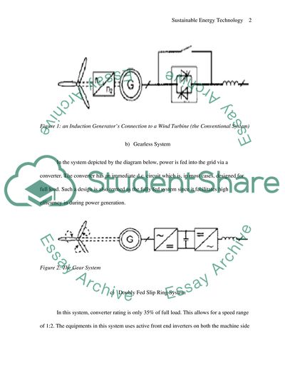
 Question 1 A. Wind Turbine Grid Connection Options Wind turbines refer to the engines that help in the transformation of wind energy into mechanical energy. The mechanical energy is then converted into electrical energy. The electrical power that is generated by the turbine is then connected to the grid system for transmission and distribution to industries, homes, and other points of utilization. The connection is done at low, medium, high, and ultra high voltages. In most cases, the turbine is connected to the grid through a medium connection. One can also use high voltage connection and this can be achieved through the use of a step up transformer. Currently, the integration of the turbine with the grid requires three connections (Armaroli & Balzani 2011, 83). They include the conventional, gearless, and the doubly fed slip ring system. a) Conventional System This system consists of an induction generator. The generator is directly connected, and this enables it to be driven by a wind turbine via a gear box. In such a case, the speed ratios of around 100 cycles per minute are attainable especially where the ratings happen to be of 1500kW and above. In order to avoid high rush-in currents after switching, it is common to have a soft-starting device. The soft-starting device consists of a phase-controlled power electronic circuit. This diagram below depicts the connection of that facilitates the power controlled circuit (MacKay & Mackay 2009, 14). Figure 1: an Induction Generator’s Connection to a Wind Turbine (the Conventional System) b) Gearless System In the system depicted by the diagram below, power is fed into the grid via a converter. The converter has an immediate d.c. circuit which is, in most cases, designed for full load. Such a design is also termed as the fully fed system since it facilitates high efficiency in during power generation. Figure 2: The Gear System c) Doubly Fed Slip Ring System In this system, converter rating is only 35% of full load. This allows for a speed range of 1:2. The equipments in this system uses active front end inverters on both the machine side and the grid side in order to allow reactive power supply and power factor adjustment during power generation and conversion (Vanek & Albright 2008, 48). Figure 3: Doubly Fed Slip Ring System Considerations for the connection system Efficiency The efficiency of the equipment as well as the protection scheme necessitates a major consideration while implementing the system. This includes the ability of the system to minimize losses while increasing the utilization of the reactive power. This can be done through use of the appropriate sizes of cables as well as other system components. Proper network configuration should also be enhanced so as to increase the level of efficiency (Johnson & Wetmore 2009, 920). Cost When designing the connection system for the application, cost of the equipment is among the major determinants. For instance, gearless connection is cheaper than any other connection that can be utilized while putting the equipment into service. The cost of the protection devices is also an important consideration since the monetary value of these devices varies (Wengenmayr 2008, 5). The Grid Voltage The Grid Voltage dictates the type and manner of connection to be used. Gearless system can only be utilized in cases where the voltage level of the generators output is compatible and it happens to be comparable to the grid voltage. In terms of protection, more complex isolation devices with higher rating should be used in high voltages. In that case, for instance, a G59 scheme requires a more elaborate protection system than a G83 scheme. G59 scheme represents a recommendation for engineering that facilitates an embedded generation. The embedded generation details how the protection requirements that facilitate generation are connected into a utility supply. With the G83 scheme, the basic generating components happen to be under/over frequency or under/over voltages where a vector shift protection device or ROCOF represent the Rate of Variation of Frequency. While a significant number of designers go for ROCOF, others prefer the Vector shift. The Vector shift enhances protection against phase loss especially at a HV-connection. For a G59 scheme, the 2MW turbine requires a more elaborate protection system (Elliott 2002, 23). Reliability The system should guarantee high degree of reliability. The protection used should be easily replaceable in case of fuses and circuit breakers. The equipment should be easy to repair. This means that the required manpower in terms of skills should be available. The spare parts of various equipment components should also be readily available, and in a useable status. The gearless system is more reliable than the rest since no gear box. The 2MW turbine requires high reliability since it is also connected to a high voltage point in the grid (Hallett & Wright 2011, 80). Part B The fault level contribution from a DG is determined by; Type of DG Distance between the generator and the fault point Presence of a voltage regulation device e.g. a transformer Network design System implemented in the integration of the DG to the network The major contribution of the generator to the grid is the voltage variation. The voltage level in the network usually determines the amount of power that is installed. These variations arise due to flickering during operation and flickering during switching. The DG also contributes to frequency variation if the appropriate stabilizers are not installed. There are various methods of reducing high fault levels. The following section elaborates some of the most common and highly utilized ones (Tertzakian 2006, 15). Up-Rating or Replacing Some Components If the fault levels exceed the set limits, some components such as circuit breakers can be up rated to suit the network demand. This method is however expensive and since it, sometimes, require the network to be reworked from the point of connection, it becomes necessary to find an elaborate method of eliminating them. It has been in use for long and it is, therefore, classified under the category that consists of the traditional methods (Tertzakian 2006, 15). Increase Line Impedance With the introduction of higher impedance components in the network, the fault levels are usually limited by the fault levels. In most cases, this is achieved through the use of current limiting reactors. Studies have indicated that this strategy is relatively a cost effective solution, but it needs some additional efforts for the purpose maintaining the voltage profile. Its biggest disadvantage is that it increases the network losses (Mathew 2011, 17). The utilization of this solution has been widespread in Netherlands but its applicability in Britain has been quite limited. In Britain, the replacement of switchgear appears to be a relatively common solution. The DG can also be connected to the network through the use of a transformer which is relatively big as this would be an enhancement to its capacity (Tertzakian 2006, 15). The limiters in use include; Fault Current Limiter The fault current limiter fires charges to open the main current circuit when a rapid rise in fault current is sensed. Its main advantage is that it retains the existing low network impedance when the network conditions are normal. It has a disadvantage in that the contacts and fuses have to be replaced after each operation and the protective relay settings have to be carefully adjusted to maintain sensitivity. This makes them expensive to implement (Mathew 2011, 17). Superconducting Fault Current Limiter It operates like a fault current limiter, but the only difference is that it has very low impedance at normal operation. However, the occurrence of a fault causes a rapid rise of the impedance; a situation which limits the current. It is also an expensive solution (Gunkel 2006, 71). Power Electronics DG types fitted with these devices provide a lower fault contribution than synchronous machines. The power ratings continue to increase as the cost reduces. PE devices do provide an additional controllability so as to improve smaller sub systems performance and provide better system functionality (HanjalicÌ et al 2008, 47-49). Solid State Fault Current Limiter Sound state fault current limiters have similar functionality with the Is limiters. In addition, they happen to be convenient for low voltage DG (MacKay & Mackay 2009, 14). Network Splitting and Reconfiguring The splitting and reconfiguration of a network reduces the fault level to great extent at a busbar. This splitting however reduces the quality of power due to increase in impedance, a situation that happens to increase the line losses. This can, however, tend to cause a low supply (Gunkel 2006, 71). Sequential Switching This is a method through which the multiple sources that contribute to any fault current are separated prior to the clearance of the faulted section. The disadvantage of using this method is that it increases the risk of sequential switching system failure. This happens due to its prevention of opening a circuit breaker before the fault current has been reduced with a sufficient measure. There is also increased dependence on information technology, a situation that increases the associated complexity (Gevorkian 2007, 73). Fault Ratings The electrical enclosures that contain bus-bars are assigned a short circuit rating as well as a fault rating. This rating is a simple and brief introduction to the pertaining concepts. During wind power generation, a significant number of products connect to 3 phase grid systems that are fed through a step-down transformer. This is often valued at 11kV local network down to a nominal value of 400V. The transformer size is determined as per the necessity of the load. Consequently, the load determines the likely fault magnitude (Gunkel 2006, 73). Question 2 Solid oxide fuelled cells (SOFC) are devices used to produce electricity directly from a fuel. This electricity is utilized for commercial, residential, industrial, and transportation purposes. They have a solid oxide or a ceramic electrolyte. They have several advantages which include high efficiency, long term stability, fuel flexibility, low emissions, and low initial cost. However they have the main disadvantages of these cells is the high operating temperature which results in delay during starting and mechanical and chemical compatibility complications (Tertzakian 2006, 15; Gevorkian 2007, 73). The first fuel cell was discovered in 1839 by Englishman W.R. Grove (1811-96). After 5kW of oxy-hydrogen fuel cells were experimented on (in 1959) by F.T. Bacon, oxy-hydrogen fuel cells were beginning to come into the spotlight. Shortly thereafter, from the 1960s-1970s, fuel cells were used by NASA in the Gemini and Apollo spaceship. Today, they are being commonly utilized during energy production (Hallett & Wright 2011, 80; Tertzakian 2006, 15). A basic SOFC consist of four layers, three of which are ceramics. A cell integrates the four layers by stacking together in just a few millimeters of thickness. Many of such cells are in a series connection, and this forms what is referred to as the "SOFC stack". The ceramics that are used in SOFCs fail to become electrically active and ionized until they attain very high temperature and the stacks run at high temperatures which ranges from 500 to 1,000 °C. Oxide ions are generated at the cathode. The ions diffuse throughout the oxide electrolyte towards the anode. At the anode they electrochemically oxidize the fuel. During the reaction, a byproduct in terms of water is released. Consequently, the electrons flow via an external circuit where they facilitate the accomplishment of some work. The cycle then repeats as those electrons enter the cathode material repeatedly (Elliott 2007, 65; Hallett & Wright 2011, 80). The electrolyte is used to conduct the negative oxygen ions from cathode to the anode. Oxidation of oxygen ions with hydrogen or carbon monoxide ions thus occurs on the anode side. Proton conducting SOFCs are developed and as this happens, the efficiency of the proton is enhanced than the situation has traditionally been. This is because they can operate even at relatively lower temperatures (Paksoy 2007, 32). They also operate at high temperature of between 500 and 1,000 °C. At these temperatures they don’t require platinum catalyst which is required for low temperature cells e.g. PEMFCs. They are also not vulnerable to carbon monoxide catalyst poisoning. This guarantees an enhancement of economical oxide-fuel cells that facilitates the reduction of emissions. Nevertheless, vulnerability to sulphur poisoning is still being observed and is removed before entering the cell through the use of absorbents (Paksoy 2007, 32). SOFCs have a wide range of application, and these applications facilitate the powering of various systems in automobiles as well as in the commercial power generation of up to 2 megawatts. The high operating temperatures makes it suitable for integration of thermal energy recovery systems in the cell, thus further increase in the overall efficiency. SOFCs use hydrogen and carbon dioxide fuels. These fuels are common in hydrocarbon fuels (Paksoy 2007, 32). SOFC results into a lower cost since precious metals are absent as compared to the proton exchanging membrane. Some other fuel cell types utilize the liquid electrolytes, and these are similar to battery acid that may, indeed, have a corrosive effect on components. Indeed, fuel cells are the third generation source of energy. Research is ongoing so as to establish which of the fuel cells can be utilized in cell phones as well as several other portable devices (McCaffrey 2008, 49-51). Despite all these advantages, the utilization of these cells still lags behind as compared to the other sources of energy. Effective utilization has only been achieved in few countries. This is due to the high cost incurred during the construction of the containment system. The SOFCs do not offer economical advantage in the generation of electricity over the widely used internal combustion engines (Gevorkian 2007, 73). Apart from hydrocarbon fuels, the alternative fuel is pure hydrogen and pure carbon dioxide which are not any cheaper. The cells still make use of non-renewable energy despite the global move to the renewable sources. This means that fuel cell power plants will use the hydrocarbon energy just like the diesel power plants, although this would happen with just a few emissions. Therefore, it will contribute a lot to the depletion of these fuels in future (Gevorkian 2007, 73). Research has, however, been ongoing in an endeavor to indentify the areas of weakness as well as the cost of materials. This will be achieved via the reduction of the SOFC temperature beyond the 600 degrees centigrade or via the development of suitable and economical SOFCs. Alternative fuels are also being considered and the design of the cell is also being improved to accommodate these fuels. Their sensitivity to impurities also calls for research since this quality adds extra cost since the fuel have to be thoroughly cleaned either in the cell or externally (Vanek & Albright 2008, 48). A little improvement in their sensitivity will enable them to use diesel in other systems of heavy trucks e.g. the refrigerated system. The startup time also poses another challenge. This is the main hindrance to the fuel cells application in mobile phones (Gunkel 2006, 71). In future, therefore, SOFC does stand a better chance of utilization than other fuel cells and their alternative means. This is greatly supported by their portability nature and fuel economics. They also don’t have complex rotator mechanical systems and this reduces their cost of maintenance (Boyle 2004, 14). They operate silently and this reduces the cost of noise reduction systems. With all these advantages, people will prefer these cells in some places for instance hospitals. It will also play a major role in energy sector after being utilized to power portable devices like mobile phones (Gunkel 2006, 71). Question 3 Wind turbine rating (Wt) = 1.5 kW From the given August line formula, Wt = (- 0.61×PV) + 2.4 a) The PV array rating (August design line) of the 1.5 kW turbine is given by; 1.5 = (-0.16× PV) + 2.4 -0.16 PV + 1.5 – 2.4 PV= = 1.4754 kWp b) The PV array rating (February design line) of 1.5 kW turbine is given by, From the given February line formula, Wt = (- 0.15×PV) + 1.7 1.5 = (-0.15×PV) +1.7 -0.15PV= -0.2 PV = = 1.33 c) The required array rating when 1 kW turbine is utilized (August design line) According to the given August line formula, Wt = (- 0.61×PV) + 2.4 1= (-0.61×PV) +2.4 -1.4 = - 0.61PV PV =  = 2.2951 kWp From the given February line formula, the required array rating when 1 kW turbine is utilized (February design line) is given by, Wt = (- 0.15×PV) + 1.7 1 = (0.15×PV) + 1.7 - 0.7 = - 0.15PV PV =  = 4.6667 kWp d) The recommendable system 1.5kw 1 kw Initial Cost £4300 £3000 PV – 5.21×1.475.4 4666.7×3.65 =£7686.834 £17633.455 Total = 11,986.834 =20033.455 According to the analysis, 1 kW turbine hybrid system is recommendable due to its economic viability. An upper PV rating has been used in both 1.5 kW and 1 kW turbine ratings so that no single point the output gives a lesser value than it is required. e) The required Amp.hr rating Daily load – 5.5 kWh For three days -5.5×3 = 16.5 kWh 16.5 kWh = 55% of the initial output 1% =  100% =  ×100 = 30 kWh = 30000 Wh Voltage = 12 V Ah rating =  = 2500 Ah Question 4 Formulation a) Wind speed on the desired height of wind turbine is given by the following calculation: Vhh = V10 ×0.19 = 6.0374m/s b) Below is a calculation of the average annual output that the project is presumed to facilitate upon its optimal conclusion. P = -0.1066×3+2.4018×2-7.6362×3.2209 =23046+87.55-46.10+3.2209 =21.5381kW c) Below are the calculations of the total yearly income and savings that would result from the implementation of the proposed project. Output = ×21.5381=18.5228 kW Annual energy = 162259.48kWh Fit payment for 20 yrs = 28.5×162259.48 =4624395.074 Fit payment for 1 year = 231219.75 pounds (162259.48×0.83) Energy sold = 134,675.37kWh × 3 pounds Gross income = 404026.11 Site electricity displacement savings = 27584.11kW ×15 . = 413761.65 Annual income = £ 404026.11 Annual saving = £413761.65 Annual saving = 413761.65 +404026.11 -231219.75 £586568.01 d) The calculation of a payback period is accomplished by obtaining the division of the initial cost with average annual profit. The calculation is accomplished as indicated below. As indicated in the calculation below, the payback period is about five months. Upon the expiry of this period, the stakeholders are expected to begin drawing benefits of the investment. Payback period =  = =0.3921 of an year  e) The following computations are completed in an endeavor to calculate the income that is generated over a period of 20 years. (404026.11+413761.65)×20 =£16355755.2 over a period of 20 years Total expenditure Initial cost – 230000 Maintenance – 80000 FIT – 4,624,395.07 Total expenses = 4,934,395.07 Profit generated = 16,355,755.2-4,934,395.07 = £11,421,360.13 By finding the difference between the value of the project and the entire cost that has been incurred, it becomes possible to establish the income after the period in question. The cost incorporates the initial investment and the maintenance expenses. List of References Armaroli, N & Balzani, V 2011, Energy for a sustainable world: from the oil age to a sun-powered future, Wiley-VCH, Weinheim, Germany, 76-83 Boyle, G 2004, Renewable energy (2nd ed.), Oxford University Press in association with the Open University, Oxford, 14 Elliott, D 2002, Energy, society, and environment technology for a sustainable future (Taylor & Francis e-Library ed.), Routledge, London, 23 Elliott, D 2007, Sustainable energy: opportunities and limitations, Palgrave Macmillan, Basingstoke, Hampshire, 65 Gevorkian, P 2007, Sustainable energy systems engineering: the complete green building design resource, McGraw-Hill, New York, 73 Gunkel, D 2006, Alternative energy sources, Greenhaven Press, Detroit, 71 Hallett, S & Wright, J 2011, Life without oil: why we must shift to a new energy future, Prometheus Books, Amherst, N.Y. 80 HanjalicÌ K, Krol, RV, & LekicÌ A, 2008, Sustainable energy technologies options and prospects, Springer, Dordrecht, 47-49 Johnson, DG & Wetmore, JM 2009, Technology and society: building our socio-technical future, MIT Press, Cambridge, Mass, 920 MacKay, D & Mackay, DJ 2009, Sustainable energy: without the hot air, UIT, Cambridge, 14 Mathew, S 2011, Advances in wind energy and conversion technology, Springer, Berlin, 17 McCaffrey, P 2008, U.S. national debate topic, 2008-2009: alternative energy, H.W. Wilson, New York, 49-51 Paksoy, HO 2007, Thermal energy storage for sustainable energy consumption fundamentals, case studies and design, Springer, Dordrecht, 32 Tertzakian, P 2006, A thousand barrels a second: the coming oil break point and the challenges facing an energy dependent world, McGraw-Hill, New York, 15-18 Vanek, FM & Albright, LD 2008, Energy systems engineering: evaluation and implementation, McGraw-Hill, New York, 46-48 Wengenmayr, R 2008, Renewable energy: sustainable energy concepts for the future, Wiley-VCH, Weinheim, 5-8 Read More
Cite this document
  • APA
  • MLA
  • CHICAGO
(Sustainable Energy Technology Assignment Example | Topics and Well Written Essays - 3000 words, n.d.)
Sustainable Energy Technology Assignment Example | Topics and Well Written Essays - 3000 words. Retrieved from https://studentshare.org/technology/1776093-sustainable-energy-technology
(Sustainable Energy Technology Assignment Example | Topics and Well Written Essays - 3000 Words)
Sustainable Energy Technology Assignment Example | Topics and Well Written Essays - 3000 Words. https://studentshare.org/technology/1776093-sustainable-energy-technology.
“Sustainable Energy Technology Assignment Example | Topics and Well Written Essays - 3000 Words”, n.d. https://studentshare.org/technology/1776093-sustainable-energy-technology.
  • Cited: 0 times

CHECK THESE SAMPLES OF Sustainable Energy Technology

How Important Are innovations in DeBeers

The global energy requirement is growing continuously notwithstanding the exhaustible nature of conventional sources like coal, oil and natural gas, or even in the face of the growth of renewable sources like wind, solar, geothermal, tidal etc.... In this scenario, the conventional meaning of energy or its quantities will become obsolete.... What could be the characteristics of such energy?... The new form of energy may be something from within rather than without....
3 Pages (750 words) Research Paper

Science of Sustainability

Medicine and information technology have especially led to improved standards of living – only a couple of hundred of years ago people died... Coal is in a similar situation at the moment, with many people predicting it could last anywhere from another hundred to four hundred years (energy Watch Group).... Your Name Class Date Question 1: sustainable development is the idea that humanity needs to continue to progress, but it needs to do so in ways that will not deplete natural resources in unacceptable ways....
7 Pages (1750 words) Essay

Radio Flyer LEED Certification

The organization that majors in the manufacturing of red wagons have been known as an iconic organization following its renovation of the office space by nearly half based on the green technology.... These structures are geared towards the assisting of energy reduction in the building.... Subsequently, other additional sustainable features of the building include brick walls that are highly insulated, plumbing fixtures that are low in their flow, permeable pavers, sustainably resourced wood, furnishings, and low VOC materials....
2 Pages (500 words) Essay

What I learned and what i think about the things ive watched

Secondly, Andy Lipkis works to help Los Angeles reduce infrastructure costs that come with urban heat island and water management – linking technology, people and trees to establish a livable city.... Some of the suggestions put forward for changes include law and public policy, science and technology, consumer behavior, the design of cities and products, and faith for a shift towards a real sustainable future.... He explodes with energy during the presentation hence engaging the audience in the conversation without swaying them from the message....
1 Pages (250 words) Essay

The Sustainable Restaurant Association

The paper 'The Sustainable Restaurant Association' presents the Food Service technology Center which provides information to the commercial foodservice sector on the efficiency and performance of equipment.... In addition, FSTC offers expertise in areas such as building energy efficiency and commercial kitchen ventilation In today's food service operations, reducing energy costs can help lower the operating costs since most operations in this industry require energy....
1 Pages (250 words) Essay

Belgium Environmental Sustainability in the EU

The current technology is made up of wind turbines in the windiest areas of the country.... In Europe, the EU commission warns of a looming energy crisis and climate change; hence it is important to consider the sustainability of Belgium and determine whether it can achieve the sustainability requirements of the EU.... As a member of the EU, Belgium complies with energy policy and sustainable development policy of the EU (EREC, 2009).... Since energy is the main source of climate change, the country regulates energy and electricity products so that the companies involved behave sustainably....
2 Pages (500 words) Research Paper
sponsored ads
We use cookies to create the best experience for you. Keep on browsing if you are OK with that, or find out how to manage cookies.
Contact Us