StudentShare
Contact Us
Sign In / Sign Up for FREE
Search
Go to advanced search...
Free

Basic Instrument Familiarity and Resistor Basics - Lab Report Example

Cite this document
Summary
Electrical resistance in measured in Ohms, which is the resistance of the conductor in which the current is 1 ampere flows when a voltage of 1 Volt is applied across a conductor (Duncan and Heather 12). For resistors in…
Download full paper File format: .doc, available for editing
GRAB THE BEST PAPER97.6% of users find it useful
Basic Lab Instrument Familiarity and Resistor Basics
Read Text Preview

Extract of sample "Basic Instrument Familiarity and Resistor Basics"

The paper “Basic Lab Instrument Familiarity and Resistor Basics" is a forceful variant of a lab report on physics. The author aims to achieve basic laboratory instrumental familiarity and to understand how to work with resistors and application of Ohms Law regarding that resistance is the opposition offered to the flow of charge. Electrical resistance is measured in Ohms, which is the resistance of the conductor in which the current is 1-ampere flows when a voltage of 1 Volt is applied across a conductor (Duncan and Heather 12).

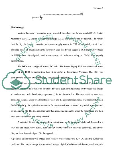
For resistors in series, the same current flows each of the resistors whereas the total sum of the voltage across each resistor equals to the total voltage applied. Therefore, the combined resistance is given by R=R1+R2+R3.RnFor resistors connected in parallel then the equivalent resistance is given by equation 4 below.In many electrical circuits, it is important to determine the rate at which electrical energy is transferred into other forms of energy. To calculate power P for electrical appliances, we find the product of the current (A) through it and the Potential difference (V) across it.

Methodology Various laboratory apparatus was provided including the Power supply(PSU), Digital Multimeter (DMM), Digital Storage Oscilloscope (DSO) and color-coded the resistor. The current limit facility, the kelvin connection split power supply system in PSU, were carefully studied and provided basics of understanding the laboratory uses of a Power Supply Unit. Simple DC voltages in DMM were investigated, and the measurement of resistance using a DMM was equally demonstrated. The DSO was configured to read DC volts.

The Power Supply Unit was connected to the input of the DSO to demonstrate how it is useful in determining Voltages. The DSO was configured to measure two separate DC voltages simultaneously. Small axial- leaded resistors were provided and using the resistor color code Figure 1 in the appendix was used to identify the resistors. The total equivalent resistance for two resistors chosen at random was calculated using equation (1) in the introduction. The two resistors were then connected in series using breadboards provided, and the equivalent resistance was measured using a DMM.

Similarly, the equivalent resistance for the two resistors connected in parallel was calculated using equation (2). The two resistors were then connected in parallel using the breadboard and their total resistance determined using a DMM. A potential divider that produced 5V output from a 12V input was made and designed in a way that the circuit drew 10mA from the 12V supply when no load was connected. The circuit diagram is as shown in figure 2 in the appendix. A potential divider from two 1Mega ohm resistors was connected to 12V DC, and the output was predicted.

The output voltage was measured using a digital Multimeter and then repeated using the oscilloscope. The values were recorded and interpreted in the results below. Using the resistor power ratings for the resistors provided, the maximum voltage applied across each resistor was determined. Results and Discussion Using equation 1 in the introduction the theoretical resistance can be evaluated as follows. R=R1+R2+R3.Rn R = (2200 + 2200) Ohms =4400 Ohms Using the Digital Multimeter the effective resistance for the series circuit connection was recorded to 4373 Ohms.

This resistance is approximately equal to the above theoretically calculated resistance. The difference in resistance could be due to the manufacturer’s errors that cannot be avoided in the manufacturing process among other factors. Similarly using equation 2 in the introduction the theoretical resistance can be calculated to be  =1100 Ohms In a similar way, the parallel resistance obtained from the breadboard parallel circuit connection was RT=1093 Ohms, which approximately equal to the theoretical effective resistance calculated.

The potential divider circuit diagram is as shown in figure 2 in the appendix. It was found out that for output of 5V from 12V with a current of 10mA a load resistance of 1700 Ohms and 500 Ohms were connected as shown in Figure 2. When the resistance across the output varies the output voltage equally varies giving a circuit that in one way resembles a sensor subsystem that likes the dark sensor that is used to switch on the light automatically in the evening. In case of load resistance variation, a shunt resistor is usually connected across the output to act as a voltage regulator.

A potential divider was made for 1M ohm resistors in which the output voltage of 6V was obtained from the 12V DC supply. The actual readings using the DMM and oscilloscope were at variance because of the operational parameters of each equipment. The maximum Voltage that can be applied across each resistor was calculated using equation 3 in the introduction as follows. For the 1M ohm resistor was calculated using equation 4 as shown. The voltage rating is higher than the one calculated because of different load resistances.

  Conclusion Understanding the operation of circuits plays an important role in electronics. Some features of circuits cannot well be understood without having a foundational hands-on experience and knowledge using laboratory apparatus. A proper reading of resistor color coding is also important in electronics as well as their properties including power ratings. Notably, the calculated theoretical values do not necessarily reflect the actual values obtained practically. This is due to variations that originate from the equipment used and errors that cannot be evaded by the manufacturer of the equipment.

Read More
Tags
Cite this document
  • APA
  • MLA
  • CHICAGO
(Basic Lab Instrument Familiarity and Resistor Basics Report, n.d.)
Basic Lab Instrument Familiarity and Resistor Basics Report. https://studentshare.org/physics/1846522-basic-laboratory-instrument
(Basic Lab Instrument Familiarity and Resistor Basics Report)
Basic Lab Instrument Familiarity and Resistor Basics Report. https://studentshare.org/physics/1846522-basic-laboratory-instrument.
“Basic Lab Instrument Familiarity and Resistor Basics Report”. https://studentshare.org/physics/1846522-basic-laboratory-instrument.
  • Cited: 0 times

CHECK THESE SAMPLES OF Basic Lab Instrument Familiarity and Resistor Basics

Physics Problems

But, if the value of resistors is different, the current through the resistor will be different, and accordingly the power dissipated by the resistor will be different.... The problem is based upon Coulomb's law.... The force between the two charges is inversely proportional to the square of the distance between them....
4 Pages (1000 words) Lab Report

Internal Resistance of a Battery

In order to determine its internal resistance accurately, this battery is connected in a series circuit with a variable resistor (rheostat) as shown in figure 1 below=battery =switch = rheostatFigure 1Source: Internal Resistance of a Battery, p 2The rheostat's resistance is then varied a number of times, taking the current and voltage readings for each turn.... The error on the internal resistance could be attributed to potential experimental errors that are pointed out elsewhere in this lab report....
4 Pages (1000 words) Lab Report

Safety management

ObjectivesTo compare and measure environmental heat index by using a digital and analog instrument.... ResultsTable 2: Analog instrument's ResultsAnalog Inst.... nnbTgTdbPreheating Cord130C220C220Caldn- Heating Cord152427Table 3: Digital instrument's ResultsDigital Int.... Table 4: Analog instrument's refined results (after repetition)Analog Inst.... nnbTgTdb1st 1313212121212nd Table 5: Digital instrument's refined results (after repetition)Digital Int....
2 Pages (500 words) Lab Report

Estimiting the half - value layer thikness

ProcedureGM-counter was assembly with the assistant of the lab technicianBackground count rate were measured three timesThe shield with the underlying source to be utilized was placed within the setup.... They possess frequency that are relatively expensive than Geiger counters and can be utilized to directly quantify the underlying magnitude… Shielding as control method is mainly utilized in reducing the external radiation hazard....
2 Pages (500 words) Lab Report

Callbration of air sampling pump

The formula normally used for determining the volume flow rate is as follows: The concept of volume flow rate of air formed the basis for this lab, whereby an air sampling pump used.... An air sampling pump was obtained from the lab technician.... Calibration of air sampling pump is a core practice in the laboratory, particularly in the process of determining the concentration of a particular pollutant in air....
3 Pages (750 words) Lab Report

The Internal Resistance of a Cell and Electromotive Force

The current values together with the terminal voltage are recorded after connecting the cell in series with a resistor of a lower value  … The resistor value was gradually increased to achieve different values of the terminal voltages and the current.... The addition of a resistor in the circuit drops the reading on the voltmeter voltage, v....
6 Pages (1500 words) Lab Report

Series and Parallel Connections

he voltage is divided based on the resistor values alone.... The purpose of this experiment was to test the theoretical analysis of series-parallel networks through direct measurements; measure properly the voltages and currents of a series-parallel network, and determine the reputation of measured values....
1 Pages (250 words) Lab Report

Power Supply System Design Using a Voltage Divider

The series resistor circuit is then connected to a constant source of power.... Two resistors are joined in parallel as shown in the figure belowAs can be seen from these simulated results the voltage across the load resistor was 5.... This paper "Power Supply System Design Using a Voltage Divider" focuses on the fact that the voltage divider is also referred to as potential divider....
6 Pages (1500 words) Lab Report
sponsored ads
We use cookies to create the best experience for you. Keep on browsing if you are OK with that, or find out how to manage cookies.
Contact Us