StudentShare
Contact Us
Sign In / Sign Up for FREE
Search
Go to advanced search...
Free

Driving Unipolar Stepper Motors - Lab Report Example

Cite this document
Summary
The paper "Driving Unipolar Stepper Motors" highlights that there are three ways of driving unipolar stepper motors; dual-phase excitation mode, single-phase excitation mode, or single-dual excitation mode, for different applications depending on the mode’s advantages and disadvantages…
Download full paper File format: .doc, available for editing
GRAB THE BEST PAPER91% of users find it useful
Driving Unipolar Stepper Motors
Read Text Preview

Extract of sample "Driving Unipolar Stepper Motors"

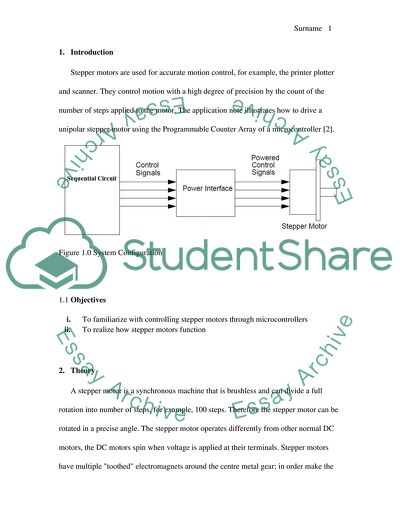
Driving Unipolar Stepper Motors Table of Contents Introduction 1 Objectives 2.Theory 3.Experimental 2 3 Tools and components 2 3.2 Procedure: Part 1 2 3.3 Procedure: Part 2 3 4.Results 4 4.1 Part I Results 5 4.2 Part 2 Results 6 5.Discussion 7 6.Conclusion 11 Works Cited 12 1. Introduction Stepper motors are used for accurate motion control, for example, the printer plotter and scanner. They control motion with a high degree of precision by the count of the number of steps applied to the motor. The application note illustrates how to drive a unipolar stepper motor using the Programmable Counter Array of a microcontroller [2]. Figure 1.0 System Configuration 1.1 Objectives i. To familiarize with controlling stepper motors through microcontrollers ii. To realize how stepper motors function 2. Theory A stepper motor is a synchronous machine that is brushless and can divide a full rotation into number of steps, for example, 100 steps. Therefore the stepper motor can be rotated in a precise angle. The stepper motor operates differently from other normal DC motors, the DC motors spin when voltage is applied at their terminals. Stepper motors have multiple "toothed" electromagnets around the centre metal gear; in order make the motor’s shaft turn, one electromagnet is powered that makes electromagnets teeth magnetically attract the gears teeth. When the gears teeth are therefore aligned to the first electromagnet, they are offset from the next electromagnet. When the next/following electromagnet is turned on, the first/previous is turned off hence the gear turns slightly to align with the next one hence the process is repeated. Each of slight rotations is known as "step," these make stepper motors to be turned in precise angle. There are two arrangements for the electromagnetic coils in a stepper motor: unipolar and bipolar; a unipolar motor has four separate electromagnets. From figure 2.0 in order to turn the unipolar stepper motor, coil "1" is given a current burst (pulse width modulated signals) then it is turned off , and coil “2” given current, and then coil “3”, “4”, to “ 1” again in a repeated pattern. The current is sent through the coils in single direction; hence ‘unipolar’ [1]. However, in the lab, the unipolar stepper motor was only used. Figure 2.0 Unipolar stepper motor 3. Experimental 3.1 Tools and components MPLAB Software; Proteus Simulation Software; Diode IN4007; power Supply; Transistors 2N2222A and TIP 121; Stepper motor; Resistors 100K and two 1K resistors; and Sequential circuit. 3.2 Procedure: Part 1 The circuit was connected as shown in the figure 3.0 below on Proteus ISIS program. An assembly program was written for the PIC so as; when S1 is put on the motor rotates right and if S2 is put on the motor rotates left, and if neither of them is put on the motor stops. The (.hex) file was loaded to PIC18f4550 family microcontroller found in the Proteus ISIS program and then the circuit simulated. The program was rewritten for stepper motor with 2 coil excitation. Figure 3.0 Proteus ISIS simulation circuit 3.3 Procedure: Part 2 The schematic below in the figure 3.1 below, a power interface was placed between the microcontroller (sequential circuit) and a stepper motor. The motor coils were connected with centre-tapped windings to a 12V power supply. The stepper motor was opto-isolated from microcontroller unit with great caution, to protect it from signal noises [6]. The transistor (2N2222A) assisted in driving enough current in 4N37 led through 1kΩ resistor. The stepper motor power was given through 12V power supplied via TIP121 transistor. The diode on stepper motor coil was used to prevent inductive kicks that occur when coil goes off. Figure 3.1 Power Interface Software for the application was written in C language in order for the motor to turn counter-or clockwise direction in the half step mode. Speed was taken into consideration when sketching the C program hence the following calculations was used: Speed= SPEED= Speed of the motor’s rotation per minute Fosc=Oscillator’s frequency NBSTEP=Step of the motor The lab motor was rated 200 steps, and oscillator used was 12 Mhz, Speed 12.2 RPM The aim of the above calculations was to ensure compatibility of components [7]. 4. Results 4.1 Part I Results Figure 4.0 Simulated Model circuit The stepper was controlled with two commons, figure 4.0, connected to the ground, and a delay was added between each signals send to terminals A, B, C, D. The following tables were observed. Single Phase Excitation Mode of Unipolar Motor Dual Phase Excitation Mode of Unipolar Motor A B C D A B C D 1 ON (1) OFF OFF OFF ON ON OFF OFF DELAY DELAY 2 OFF ON OFF OFF OFF ON ON OFF DELAY DELAY 3 OFF (0) OFF ON OFF OFF OFF ON ON DELAY DELAY 4 OFF (0) OFF OFF ON ON OFF OFF ON Table 4.0 Results for Single Phase Excitation Mode and Dual Phase Excitation Mode Single-Dual Excitation Mode A B C D 1 ON OFF OFF OFF DELAY 2 ON ON OFF OFF DELAY 3 OFF ON OFF OFF DELAY 4 OFF ON ON OFF DELAY 5 OFF OFF ON OFF DELAY 6 OFF OFF ON ON DELAY 7 OFF OFF OFF ON DELAY 8 ON OFF OFF ON Table 4.1 Single-Dual Excitation Mode 4.2 Part 2 Results It was observed in Part 2, the Dual phase excitation mode made the motor rotate at much greater torque as compared to the single phase excitation mode. Figure 4.1 Single Phase Excitation Mode Figure 4.2 Dual Phase Excitation Mode Figure 4.3 Single-Dual Excitation Mode 5. Discussion From the tables 4.0 and 4.1, the stepper responded to series of signal through its rotation in specific direction; reverse ordered signals led the motor to rotate in an opposite direction. The difference between the two coil excitation and one coil excitation is that, the two coil excitation provides the motor great torque rotations [5]. Figure 5.0 Single Phase Excitation Mode In single phase excitation mode, each successive coil was energized in turn. Single phase excitation modes produced smooth rotations and consumed less power, less torque is given from the rotations, of the three modes. Steps were applied in order from 1 to 4. After the fourth step, the sequence was repeated from first step. Application of steps from 1 to 4 made the motor run clockwise, while reversing the order of step from 4 to 1 made the motor run counter-clockwise. Figure 5.1 Dual Phase Excitation Mode In dual phase excitation mode, successive pairs of adjacent coils were energised in turns, motion were not as smooth compare to single phase excitation mode; power consumption was high, due to greater torque. As in single phase excitation mode, application of the steps in the order made the stepper motor run clockwise while reversing order made it turn counter-clockwise. The Single-Dual excitation mode sequence was a mix of single phase excitation mode and dual phase excitation mode. The mode had an advantage because it increased by two the stepper motor’s nominal number of steps. The practice unipolar stepper motor had 24 steps of 15 and was each turned into half step mode of 48 steps of 7.5. Figure 5.2 Single-Dual Excitation Mode The centre tap on the stator winding allowed the current in the coil to alter direction when the windings were grounded. The magnetic property of the stator changed and it selectively attracted and repelled the rotor, thereby resulted in a stepping motion for the motor. In the half-stepping, the motor used half its actual step angle, the motor was rated 15 degrees per step; the motor was programmed to rotate at 7.5 degree per step. Micro-controller could not generate enough current for the stepper motor coils; hence the drive ULN2003 was utilized in driving the motor. The Programmable Counter Array (the PCA) of the microcontroller was used in Part 2 to generate the control signals for the Power Interface (the PI). The PI allowed the microcontroller in use to drive enough current into the coils of the stepper motor. The PCA provides greater accuracy than toggling pins found in the software since the toggle is evident before an interrupt request is worked on. Thus, interrupt response time did not affect the accuracy of the output. In the PCA, the microcontroller’s CPU (central processing unit) is left free for the application task execution when the PCA is driving stepper motors [4]. 6. Conclusion From the results, a stepper motor responds to series of signals by rotating in specific direction; when the signal is reversed, the motor rotates in the opposite direction. There are three ways of driving a unipolar stepper motors; dual phase excitation mode, single phase excitation mode, or single-dual excitation mode, for different applications depending on the mode’s advantages and disadvantages. In a unipolar motor configuration, the dual phase excitation mode has greater torque as compared to the single phase excitation mode. Works Cited [1]T. Brezina and R. Jablonski, Recent Advances in Mechatronics. Berlin, Heidelberg: Springer-Verlag Berlin Heidelberg, 2010. [2]W. Bolton, Programmable logic controllers. Amsterdam: Elsevier/Newnes, 2006. [3]H. Huang, PIC microcontroller. Clifton Park, NY: Thomson/Delmar Learning, 2005. [4]A. Hughes and B. Drury, Electric motors and drives. Oxford: Newnes, 2013. [5]C. Xia, Brushless DC motor drives. Hoboken, N.J.: Wiley, 2012. [6]K. Kumar and B. Umashankar, The 8085 microprocessor. Delhi, India: Dorling Kindersley (India), 2008. [7]S. Ghoshal, 8051 microcontroller. New Delhi: Dorling Kindersley, 2010. Read More
Cite this document
  • APA
  • MLA
  • CHICAGO
(Driving Unipolar Stepper Motors Lab Report Example | Topics and Well Written Essays - 1250 words, n.d.)
Driving Unipolar Stepper Motors Lab Report Example | Topics and Well Written Essays - 1250 words. https://studentshare.org/logic-programming/1853936-digital-circuit-design
(Driving Unipolar Stepper Motors Lab Report Example | Topics and Well Written Essays - 1250 Words)
Driving Unipolar Stepper Motors Lab Report Example | Topics and Well Written Essays - 1250 Words. https://studentshare.org/logic-programming/1853936-digital-circuit-design.
“Driving Unipolar Stepper Motors Lab Report Example | Topics and Well Written Essays - 1250 Words”. https://studentshare.org/logic-programming/1853936-digital-circuit-design.
  • Cited: 0 times

CHECK THESE SAMPLES OF Driving Unipolar Stepper Motors

Analysis of The Gate to Womens Country Book by Sheri Tepper

Evolutionary gender theories claim that man and woman are dissimilar in a physiological way as well as psychologically.... Historically, men are viewed as breadwinners and hunters, who are aggressive and dominant, while women are treated as 'gathers', who are cooperative and able to find consensus in each disagreement....
4 Pages (1000 words) Essay

Single phase motors

Single-phase motors find us in vast applications ranging from home to small farms and industries.... However, the… Since most of the motor failure and other problems arise from the mismatch of the motor type with required application, a few types Report by ashok kaul Single Phase motors When the availability of three-phase power is unreliable and the cost is a major factor, single-phase motor is the best alternative to use as a prime power source.... Single-phase motors find us in vast applications ranging from home to small farms and industries....
2 Pages (500 words) Essay

Problems faced by Grandiose Motors

In the paper “Problems faced by Grandiose motors” the author discusses the problems related to space availability and inventory management of the company.... A major factor, which Felix Fabulous has extracted out, which could cause problems to the company is the inventory management system of the spare parts which are used in after sales service, one of the most important reasons why customers prefer Grandiose motors over its competitors.... In light of this, Grandiose motors faces the following problems related to space availability and inventory management: All the parts had different levels of demand and different suppliers; hence the company had to deal with many suppliers at the same time....
11 Pages (2750 words) Essay

Tata Motors

The project “Tata motors” discusses Tata motors which is a leading automobile company producing commercial and passenger vehicles in India.... The areas which have been analyzed in the project are the organizational structural and behavioral issues that evolved in Tata motors due to the acquisition....
2 Pages (500 words) Essay

Memorandum for Motor Driving Schools

This paper 'Memorandum for Motor driving Schools" focuses on the fact that the author would like to brief on the progress of the project on the use of mobile phones by driving instructors while conducting behind the wheel lessons.... nbsp; The group has visited major motor driving schools in the states to assess the quality of training they offer to citizens so as to give recommendations to COMAR which is a body responsible with road safety....
1 Pages (250 words) Assignment

Careless Driving

The author of the following paper "Careless driving" comments on the threats of careless driving.... … A driver has the legal duty of care towards every other driver, vehicle or person on the road and so driving carelessly can result in a severe legal action (Hess 148).... The rate of accidents caused by reckless driving is increasing day by day in America and in other parts of the world.... The law in Texas for careless driving has the authority to impose heavy fines, sentenced to jail for 6 months or suspend the driving license for about two years....
7 Pages (1750 words) Research Paper

Causes and Effects of Drunk Driving

driving while under the influence of alcohol or drug intoxication is very dangerous and as such is illegal in the United States of America and many other countries.... a wide body of research exists which shows correlation between alcohol and reaction times, driving performance and… Many states of the United States have laws the make it illegal for any person to drive with a blood alcohol concentration exceeding 10%.... This is because by driving while drunk one not only poses danger to him/herself, but also to DUI: Cause and Effects....
2 Pages (500 words) Essay

Mechanical Device: Stapler

This paper "Mechanical Device: Stapler " describes the stapler refers to a mechanical device that has a top part that is pressed downwards, a body and a base or bottom part when being operated (Stapler, n.... ).... A stapler is also held by hands during operation.... hellip; A stapler has different parts, and these parts include the body, base with the anvil, staple's magazine, leaf spring, helical coil spring, raceway, rear pin joint,  blade and staple exit....
3 Pages (750 words) Assignment
sponsored ads
We use cookies to create the best experience for you. Keep on browsing if you are OK with that, or find out how to manage cookies.
Contact Us