StudentShare
Contact Us
Sign In / Sign Up for FREE
Search
Go to advanced search...
Free

Combinational and sequential logics - Assignment Example

Cite this document
Summary
The logic gates add up to six. The Ex-OR gate produces “1” at the output when either of the input is at logic 1. AND gate is used when both inputs are at logic 1. The adder truth table comprises of the additional column that caters for the summed output, carry output, and carry-in input (Ross & Sheldon 75). …
Download full paper File format: .doc, available for editing
GRAB THE BEST PAPER93.5% of users find it useful
Combinational and sequential logics
Read Text Preview

Extract of sample "Combinational and sequential logics"

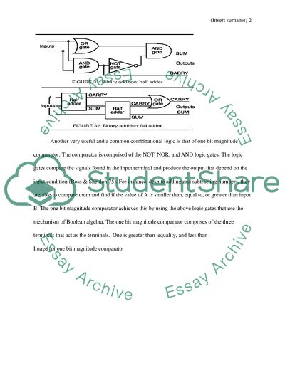
? Combinational and Sequential Logics Task Learning Outcome 1 Interpret manufacturer’s data to select appropriate combinational logic devices for specific purposes There are various logic gates that are used in designing and building of a two binary digits full adder. The logic gates for designing and building of a full adder includes three Ex-OR gates, one OR gate, and two AND gates. The logic gates add up to six. The Ex-OR gate produces “1” at the output when either of the input is at logic 1. AND gate is used when both inputs are at logic 1. The adder truth table comprises of the additional column that caters for the summed output, carry output, and carry-in input (Ross & Sheldon 75). The two binary digit full adders are found as the standard IC packages as 74LS283 and 74LS83 which add up and generate a CARRY and SUM output. Image for the two binary digits full adder Another very useful and a common combinational logic is that of one bit magnitude comparator. The comparator is comprised of the NOT, NOR, and AND logic gates. The logic gates compare the signals found in the input terminal and produce the output that depend on the input condition (Ross & Sheldon 75). For instance, despite adding and subtracting numbers, they are able to compare them and find if the value of A is smaller than, equal to, or greater than input B. The one bit magnitude comparator achieves this by using the above logic gates that use the mechanism of Boolean algebra. The one bit magnitude comparator comprises of the three terminals that act as the terminals. One is greater than equality, and less than Image for one bit magnitude comparator For the less and greater: in the cases that are worst, the answer is written in the form of a sum of products and change them into NAND gates. Using DeMorgan, Task 2-Learning Outcome 1.2 Compare the characteristics of similar devices using different technologies a) The two similar devices manufactured by two different manufacturers are: open collector hex inverter and Triple three-input NOR gate and uses the transistor- transistor technology. The devices have better immunity to damages because of static electricity discharges. The devices also have a fair immunity to noise, good speed, and have a better “fan-in” and “fan-out”. The devices can easily introduce variations in the supply of power when the device changes the state of logic and draws a greater current load. This results in wrong triggering and switching of the devices. Because of the importance in interconnection and component layout, the devices use the decoupling capacitors. They devices also require more than five volt supply of power called the Vcc and their IC can easily be destroyed if the power supply is exceeded. b) The two devices can easily be recognized by the parameter numbers. Open collector hex inverter consists of five digits and begins with seven do not while triple three-input NOR gate consists of the five digits and begins with number five. The letter codes for the open collector hex inverter are inserted into Transistor- transistor Logic part numbers after the second digit to show the sub-family of the device. However, the triple three-input NOR gate have no codes inserted into the technology rather they have similar pin connections and operate as ordinary devices despite being operationally different and cannot be employed in equal fashion as the ordinary TTL devices (Henderson & Shane 83). The open collector hex inverter has an output resistor that is integrated into it to offer lower output impedance despite low or high output. While the Triple three-input NOR gate has no transistors. When using an open collector hex inverter, an outside resistor has to be used between any other device and the output. The advantage of this device is that various outputs can be hard-wired together for one output this is totally different from the Triple three-input NOR gate. c) Below is the data that is obtained from the manufacturer’s data sheet From the above it is depicted that the devices two polar transistors. The main differentiating characteristics of the fundamental Transistor- transistor family is because they consume a lot of power close to above five volts, and they use high currents to drive their level of logic below IV incase logic is zero or lower and above approximately 3.5 volts for logical that is approximately one or high. A specific feature for the technology signal is that the gate’s input rise to a logical 1 if it is not connected. Meaning, the major requirement for driving this technology is to pull down its level to zero. Task 3- Learning Outcomes 1.3 Design, construct and test combinational circuits Q1) Truth Table A B C F 0 0 0 0 0 0 1 0 0 1 0 1 0 1 1 1 1 0 0 0 1 0 1 1 1 1 0 0 1 1 1 1 The sum of products expressions include 3rd row: 4th row: 6th row: 9th row: Boolean Expression Output = The above expressions can be implemented using the combinational AND, OR, NOT gates as shown in the diagram below Q2 A two digit binary full adder becomes crucial when the carry input is added to the binary digits to come up with the correct sum. Adder that is half do not have input for the carries from the earlier circuits. One method for constructing the two digits full adder is to employ 2 half adders and OR gates. The inputs B and A are applied to gate 1 and gate 2. When added they make up one half of the adder. The summation of half adder output and the carry from the earlier circuit becomes the inputs used on the 2nd half of the adder. The carry from the two half’s is applicable to gate five to produce the circuits carry-out. The expression for the full adder would be When carry in, A, and B are all high, the summation of and then carry out will be produced. The truth table is shown in the figure above. Q3 After building and testing the full adder with the wave form, the input and output can be assigned for the design (Gibson 92). The full adder will be applied on them, with Cin representing the carry. Assuming that a is 0 and b is 0 then the output will be the summation S and Cout. This will represent the functionality of the full adder. After simulation, someone will be able to see the input and output that was keyed in the test wave form. The illustrated results are as shown below. Task 4 – Learning Outcome 1.4 Use computer software packages to simulate logic circuits In task 3, full adder was designed using the VHDL. This section demonstrates testing of the design and continues to show the assign pins. The full adder represents a combinational output that develops the arithmetic summation of three bits. It comprises of the three inputs and four outputs. The inputs are a and b and Cin is the carry. The output denoted as S is the summation of 3 bits and Cout is denoted as the carry. The full – adder design is shown in task 3. The software’s code is as shown below. Simulation under the Test Bench Wave Form After creating the test using the waveform you will be able to see and design the output and input of the design as shown in the below illustration. Image 1: Input simulation The above number will be applicable to the full adder and Cin is denoted as the carry. If a= zero and b zero then the output will be the summation of S and Cout that 0 and 1 respectively. When the above is applied the functionality will work. Finally after the simulation process, one will be able to see both the output and the input that is put on the test waveform as shown below. Image: output simulation The results for assigning input output pins. Signals Elements on the board( XSA-200) Pin( Xc1s200 FPGA) Input a Sw1 1 P11 b Sw1 2 M10 Cin Sw1 3 R11 Output S Segment A G16 Cout Segment B F15 Reference Gibson, G. A.. Microcomputers for engineers and scientists. 2. ed. Englewood Cliffs: Prentice-Hall, 1987. Print. Henderson, Shane G.. Simulation. Amsterdam: Elsevier, 2006. Print. Ross, Sheldon M.. Simulation. 4th ed. Amsterdam: Elsevier Academic Press, 2006. Print. Read More
Cite this document
  • APA
  • MLA
  • CHICAGO
(“Combinational and sequential logics Assignment Example | Topics and Well Written Essays - 1250 words”, n.d.)
Retrieved from https://studentshare.org/logic-programming/1490276-combinational-and-sequential-logics
(Combinational and Sequential Logics Assignment Example | Topics and Well Written Essays - 1250 Words)
https://studentshare.org/logic-programming/1490276-combinational-and-sequential-logics.
“Combinational and Sequential Logics Assignment Example | Topics and Well Written Essays - 1250 Words”, n.d. https://studentshare.org/logic-programming/1490276-combinational-and-sequential-logics.
  • Cited: 0 times

CHECK THESE SAMPLES OF Combinational and sequential logics

Importance of Psychological Research and Contribution to Our Society

The paper "Importance of Psychological Research and Contribution to Our Society" states that years of sequential studies have given us definite predictive patterns that people can relate to and use in daily life, bringing new dimensions and factors in building a stable society....
7 Pages (1750 words) Essay

Personal Effectiveness Report

Different personality characteristics cause different ways in works.... Personality characteristics are unique for each and every one.... As such, working in a team… However, they have characteristics and different ways to do things, as such, the report does not ascertain accurately the characteristics, it is a collection of data assembled together and assessed from the two Table of contents 0 Introduction 1 Purpose 2 Scope of Limitations 3 Background 2....
2 Pages (500 words) Assignment

Circuit to Control a Traffic Signal

The aim of the paper “Circuit to Control a Traffic Signal” is to design and implement a sequential circuit using JK flip flops and control the working of a traffic signal having the following characteristics.... The basic storage element in a sequential logic is called the flip-flop.... Also, the hardware required in sequential circuits is considerably lesser when compared to a combinational circuit undertaking the same task.... After designing the counter using the desired flip flop, he designed a combinational circuit for the light outputs....
6 Pages (1500 words) Assignment

The Product Development Processes

A fundamental problem in managing product development is the optimal timing, frequency, and fidelity of sequential testing activities.... The sequential development method is a consecutive action accomplishing the process of production while Concurrent Engineering meets the requirement of simultaneous development of the product....
14 Pages (3500 words) Assignment

Principles of Digital Computing

The objective of this research under the title "Principles of Digital Computing" is the pursuance of the history of digital computation technology, its design, impacts, and its comparison in terms of advantages and disadvantages with analogue computing.... nbsp;… An insight into the early years of the nineteenth century throws light upon the evolution of digital design theory....
7 Pages (1750 words) Research Paper

Design of a Motor Speed Sampling, Amplification, Filtering and Display Circuit

The design of the electronics circuit makes up a combinational digital circuit that will be applied in sequential logic.... The paper "Design of a Motor Speed Sampling, Amplification, Filtering and Display Circuit" states that using the input signals, the ripple counter was reset to 0 as required....
11 Pages (2750 words) Coursework

Digital Electronic System

UART receives parallel bytes of data from the computer and transmits the individual bits in sequential form.... This lab report "Digital Electronic System" discusses the design and simulation of Asynchronous Serial Data Transmission using the multi sim software.... It covers the various design methods including Parallel to serial conversion; use of higher-level logic constructs, for this case, the multiplexers....
7 Pages (1750 words) Lab Report
sponsored ads
We use cookies to create the best experience for you. Keep on browsing if you are OK with that, or find out how to manage cookies.
Contact Us