StudentShare
Contact Us
Sign In / Sign Up for FREE
Search
Go to advanced search...
Free

The Layout and Operation of a Piston Engine - Assignment Example

Cite this document
Summary
This assignment "The Layout and Operation of a Piston Engine" shows that most marine engines in the shipping industry use Piston Engines that run on Diesel or a mix of diesel and Heavy oil, alternatively called blend oil. These engines are quite robust in size…
Download full paper File format: .doc, available for editing
GRAB THE BEST PAPER93.8% of users find it useful
The Layout and Operation of a Piston Engine
Read Text Preview

Extract of sample "The Layout and Operation of a Piston Engine"

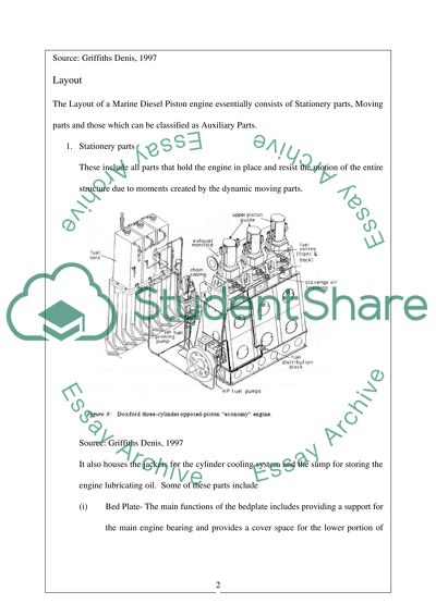
?The Layout and Operation of a Piston Engine 510942) Introduction Most marine engines in the shipping industry use the Piston Engines that run on Diesel or a mix of diesel and Heavy oil, alternatively called blend oil. These engines are quite robust in size since these generate power to the tune of 30,000 bhp but at relatively low ranges of the rpm. This usually varies between 60-100 rpm since drag forces on the propeller increase at high rpm’s. The Sulzer low speed marine piston engine specifically designed for crude oil tankers has been discussed in the next segment. Source: Griffiths Denis, 1997 Layout The Layout of a Marine Diesel Piston engine essentially consists of Stationery parts, Moving parts and those which can be classified as Auxiliary Parts. 1. Stationery parts These include all parts that hold the engine in place and resist the motion of the entire structure due to moments created by the dynamic moving parts. Source: Griffiths Denis, 1997 It also houses the jackets for the cylinder cooling system and the sump for storing the engine lubricating oil. Some of these parts include (i) Bed Plate- The main functions of the bedplate includes providing a support for the main engine bearing and provides a cover space for the lower portion of the crankcase. The sump for the lubricating oil is also contained in this area. (Anderson Henrik, 2007) (ii) Main Bearings- This supports the crankshaft and takes up the load that is transmitted from the piston onto the crankshaft. Explosions or unequal generation of torque can affect the bearing severely which can be easily replaced thus preventing replacement of the entire crankshaft.( Calder Nigel, 1987) Source: RTA84T Sulzer Engine, 2004 (iii) Frame- This houses the entire upper portion of the crankcase and provides stability to the cylinder block. In marine engines these are also referred to as the ‘A’ Frame. (Calder Nigel, 1987) Source: RTA84T Sulzer Engine, Jack Bolts in the A frame, 2004 (iv) Cylinder Block- This supports the cylinder liners. (v) Cylinder Liner- This is most critical portion of the engine since it contains the area of combustion. The air is compressed in this region and the combustion of air-fuel mixture desired to generate power takes place. (Sulzer RTA84T, 2004) Source: RTA84T Sulzer Engine, Liner 2004 (vi) Cylinder Heads- This is the top portion of the cylinder liner and seals the liner thus creating a confined space required for combustion. (vii) Valves or Ports- The function of valves or ports is to allow the entry of fresh air required for combustion and to allow the exit of exhaust gas after the combustion is over. Valves are an additional entity usually housed on top of the cylinder head while ports are holes and openings situated on the cylinder liner which open or close according to the position of the piston skirt with respect to the cylinder liner. (Calder Nigel, 1987) 2. Moving Parts (i) Piston- The face of the piston acts as the other end of the confined space in which combustion occurs. The piston slides in and out of the cylinder contributing to each stroke of the engine. To prevent metal to metal contact between the liner and the piston sides a small clearance is maintained; the sealing achieved by a number of sealing rings housed in grooves at the upper end of the piston. The sealing ring prevents the air or exhaust gas from passing on to the underside of the piston. The bottom end of piston is called the ‘skirt’ while the upper portion is called the ‘crown’. Source:RTA84T Sulzer Engine,Pistons, 2004 (ii) Connecting rod- The connecting rod can be construed as a bar which has bearings at both ends. It acts as an interface between the piston and the crankshaft. The thrust developed on the piston is transmitted to the crankshaft via the connecting rod. (Anderson Henrik, 2007) (iii) Connecting Rod Bolts- The connecting rod connected to the crankpin of the crankshaft has a split bottom end. This split end is held in place by these bolts. (iv) Crankshaft- The reciprocating motion of the piston in the cylinder liner is converted to a rotary motion of the crankshaft which ultimately coupled with a flywheel generates the rotating motion of the propeller used in ship propulsion. (Calder Nigel, 1987) Source: RTA84T Sulzer Engine, Crankshaft, 2004 (v) Flywheel – In a five cylinder main engine the combustion cycle in all five cylinders is distributed and does not occur at the same time. However, it is difficult to attain uniform power generation at all points of cycle. A Flywheel stores up additional kinetic energy during the power stroke and releases the same during a lean period thus contributing to uniform turning moment of the propeller shaft. (Sulzer RTA84T, 2004) 3. Auxiliary Parts (i) Fuel Injection Pump- The fuel injection pump coupled with a fuel injection nozzle housed in the cylinder head atomises the fuel into fine mist as it enters the cylinder. This ensures complete homogenous mixing of these fuel droplets with the hot air and also ensures complete burning of fuel. (ii) Camshaft- The camshaft geared to the crankshaft houses a number of cams. These cams are primarily used in operating the fuel injection pump. The shape and orientation of these cams on the camshaft help in operating the fuel pump for each cylinder just prior to the required point of combustion. (Sulzer RTA84T, 2004) (iii) Governor- The governor controls the amount of fuel that is to be provided to the engine to maintain it at the desired rpm. This is because load on the propeller keeps on changing with the sea current and the propeller depth below sea level, which can lead to fluctuating rpm’s. (Calder Nigel, 1987) (iv) Turbocharger- It has been found out that supplying pressurised air in the air intake into the cylinder improves engine efficiency considerably. Modern marine diesel engines use the exhaust gases to operate a turbocharger which sucks the air and provides it with a higher pressure into the cylinder inlet. An intercooler provided between this turbocharger and the liner inlet allows for more condensed pressurised air to be drawn via the scavenge space. (Calder Nigel, 1987) (v) Safety Devices- Apart from the above devices the engine is protected from failure via various relief valves and oily mist detectors placed in the crankcase. These safety devices detect anomalies and prevent the engine from overpressure and explosion. (vi) Piping systems and manifolds are provided for the supply and removal of exhaust gases, cooling water and lubricating oil. Operation The two stroke diesel engine derives its name from the fact that only two strokes of the piston are required to finish one working cycle as compared to four strokes required by a four stroke engine. The downward motion of the piston is called the power stroke while the upward motion is called the compression stroke. A series of ports arranged in two layers at about the mid portion of the liner are called the exhaust and scavenge ports. These two stroke diesel engines has the air starting valve, relief valve and the fuel injection valve housed in the cylinder head but do not have any inlet or exhaust valves. The piston which has a skirt attached to its bottom uncovers the scavenge ports and the exhaust ports. As the scavenge ports are uncovered by the piston skirt, a charge of fresh air which is at a higher density and pressure than the exhaust gas in the liner space enters into the manifold via the scavenge ports. This air pushes the remaining exhaust gases through the exhaust port providing fresh air for the next cycle of compression. Valve Timing Diagram and the Cycle of Operations The figure shown below explains in detail the sequence of events in the working of a two stroke diesel marine piston engine. (Valve Timing Diagram, n.d) Source: Valve Timing Diagram, n.d (i) As the piston moves up from the bottom dead centre (BDC) it closes both the scavenge ports and the exhaust ports at 40? and 50? after the BDC. The fuel valve remains closed and this air is pressurized to about 35 bar attaining a temperature of 540?C after compression. (ii) At 10? before the piston reaches top dead centre (TDC) the fuel pumps in fuel through the fuel injector into the cylinder. This fuel in the form mist mixes with the compressed air producing heat and generating thrust for the power cycle. This expansion produced as a result of this combustion forces the piston to move down. By the arrangement of the cam the fuel pump is designed to stop pumping fuel at 30? degree after the TDC. As the gases expand it pushes the piston further down thus producing the reciprocating motion of the piston. (iii) As the piston moves down and reaches 40? before BDC, it uncovers the exhaust ports. The availability of an exit forces this exhaust gases out causing a severe drop in pressure in this region. (iv) The piston now moving further down on reaching 30? degree before BDC uncovers the scavenge ports. These scavenge ports admits fresh air and it being at a higher pressure compared to the combusted air generates a natural draft which forces the remaining exhaust gases through the exhaust port. To assist in inducing this natural draft further, the piston has a small hump to direct the air upward. The scavenge ports on the liner are also cut tangentially to create a swirling motion of air which cleans up the area from exhaust gases. (Valve Timing Diagram, n.d) (v) After the piston reaches the bottom dead centre it begins it upward movement once again and the entire cycle is repeated. Conclusion The two stroke engine is generally used in most marine main engines since power is generated in two strokes of the engine. Using exhaust and scavenge ports mitigate the requirement of valves. This therefore reduces the problems arising from wear and tear along with improper seating of valves. However, the disadvantage lies in the fact that lubricating oil from the crankcase sump used to lubricate liners can enter the scavenge space causing scavenge space fires. Wear in the piston skirt can allow the exhaust air to enter the crankcase. If there are any hot spots that have developed in areas of the crankcase, it can cause serious explosions. (Griffiths Denis, 1997) Since there are chances of the crankcase oil getting contaminated from the combustible gases and the acids formed from sulphur compounds in fuel, proper chemicals need to be added to prevent this contamination. The two stroke piston marine engine is undergoing more developments to improve its mechanical efficiency and at the same time provide more robustness which results in minimal breakdown. The Sulzer RTA84T low speed marine diesel engine (Sulzer RTA84T, 2004) which has been discussed here is step in that direction. Reference Lists 1. Anderson Henrik, 2007, Structural Design of a two-stroke diesel engine, New Design Department, Research & Development MAN Diesel A/S. 2. Calder Nigel, 1987, Marine Diesel Engines: Maintenance, Troubleshooting and Repair, International Marine Publishing. 3. Griffiths Denis, 1997, British Marine Industry and the Diesel Engine, The Northern Mariner 4. Sulzer RTA84T, 2004, Technology Review, Wartsila, Available at http://wartsila.com, [Accessed on 15th March 2011] 5. Valve Timing Diagram, n.d, The basics of the 2 Stroke Diesel Cycle, Available at http://www.marinediesel.co.uk, [Accessed on 15th March 2011] Read More
Cite this document
  • APA
  • MLA
  • CHICAGO
(“The layout and operation of a piston engine Assignment”, n.d.)
Retrieved from https://studentshare.org/family-consumer-science/1411250-the-layout-and-operation-of-a-piston-engine
(The Layout and Operation of a Piston Engine Assignment)
https://studentshare.org/family-consumer-science/1411250-the-layout-and-operation-of-a-piston-engine.
“The Layout and Operation of a Piston Engine Assignment”, n.d. https://studentshare.org/family-consumer-science/1411250-the-layout-and-operation-of-a-piston-engine.
  • Cited: 0 times

CHECK THESE SAMPLES OF The Layout and Operation of a Piston Engine

The Environment Impact of Electric Vehicles

Source: Shim et al, 2009, Electric car-Tesla Roadstar Structure and Layout of the two vehicle systems In an electric engine the numbers of components is fewer in number and are simpler in configuration.... (Markel Tony, 2007) Compared to the IC engine which had power sources taken from the same shaft drive it is essential that power for operating the air conditioner and water pump are taken from individual separate motors.... (Basic Electric Car engine Overview, 1999) The Internal combustion on the other hand has a number of components that are required for its efficient working....
6 Pages (1500 words) Essay

Operation management

Operations management is also involved in the operation and design of systems for production, transport, service or supply.... perations management facilitates collaboration among operation management professionals and other executives and managers in order to establish how operational planning can improve and sustain an organization's long-term marketing strategy.... Nestlé's operations, for example, take into consideration the manufacturing layout....
8 Pages (2000 words) Essay

Thermoacoustics

This essay focuses on the analysis of the Stirling cycle machine and Stirling engine, that were invented in 1816 by Robert Stirling in Scotland, some 80 years before the invention of diesel engine, and enjoyed substantial commercial success up to the early 1900s.... This essay provides a literature review on Stirling engine technological development.... Number of research works on the Stirling engine is discussed.... The aim of this research is to find a feasible solution, which may lead to a preliminary conceptual design of a workable Stirling engine....
17 Pages (4250 words) Essay

NASA General Aviation Propulsion Diesel Engine

the layout and the engine capacity of the aircrafts have changed from two –stroke to four strokes.... Teledyne Continental Motors, Aerosance Cirrus Design, Hartzell Propeller, Lancair and Mod Works together partnered with NASA to develop diesel engine, an advanced piston engine.... The aim of the program is to develop an innovative engine which ushers in affordability, comfort and reduced cost for the aviation industry.... The new engine is to reduce noise and vibrations and load on pilot for monitoring the plane, thereby adding greater comforts to the passengers....
5 Pages (1250 words) Research Paper

Layout and Operation of a Jet Engine

This paper 'layout and operation of a Jet Engine" focuses on the fact that at the beginning of the 13th century, Chinese invented rockets by using the physical principle of action-reaction.... The practical application of stream turbine was widely appreciated when the practical application of the steam engine was dominating (Hunecke 2011).... Categorized as turbojet, turbofan, turboprop, or turboshaft engine, the gas turbine engines are the most significant breakthrough in the history of aviation....
9 Pages (2250 words) Case Study

Aircraft fuel system

Supervisory engine management was developed along with the advent of computer technology with a view to reduce the cognitive load of pilots and to extend the engine life (Nagabhushana and Sudha 187)....
7 Pages (1750 words) Coursework

Manufacturing process

Bore is the system is the diameter of each cylinder that is Stroke is the length of travel of rod or piston.... Deck height volume is obtained from getting the area between the top of the piston and the top of the block when the piston is at the top of the stroke.... he existing layout consists of a water pump, an alternator and a vibration of damper or there is sometimes the use of crank shaft pulleys....
5 Pages (1250 words) Lab Report

Noise Measuring System and Analysis Techniques for Diesel Engines

The "Noise Measuring System and Analysis Techniques for Diesel Engines" paper discusses some major aspects concerning the noise measuring system and analysis techniques with regard to a diesel engine.... Some of these aspects cut across the measurable parameters for monitoring the condition of an engine.... For this research, a typical diesel engine will be considered by looking into the strategies and parameters that can be measured in order to monitor it....
15 Pages (3750 words) Lab Report
sponsored ads
We use cookies to create the best experience for you. Keep on browsing if you are OK with that, or find out how to manage cookies.
Contact Us