StudentShare
Contact Us
Sign In / Sign Up for FREE
Search
Go to advanced search...
Free

Layout and Operation of a Jet Engine - Case Study Example

Cite this document
Summary
This paper 'Layout and Operation of a Jet Engine" focuses on the fact that at the beginning of the 13th century, Chinese invented rockets by using the physical principle of action-reaction. Rocket technology started maturing after World War II which made the idea of space travel a possibility. …
Download full paper File format: .doc, available for editing
GRAB THE BEST PAPER95.4% of users find it useful
Layout and Operation of a Jet Engine
Read Text Preview

Extract of sample "Layout and Operation of a Jet Engine"

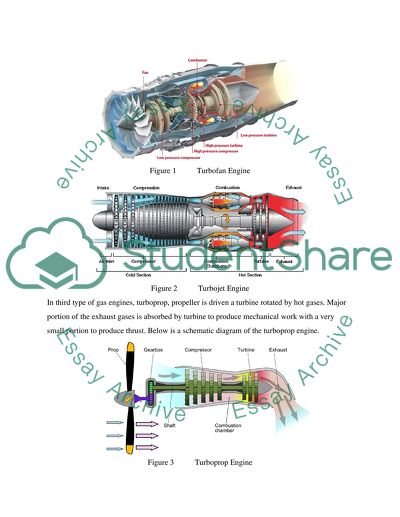
Layout and Operation of a Jet Engine INTRODUCTION In the beginning of thirteenth century, Chinese invented rockets by using the physical principle ofaction-reaction. Rocket technology started maturing to a state after World War II which made the idea of space travel a possibility. In similar pattern, idea of stream turbine first surfaced in the seventeenth century; however, its practical application was first employed in twentieth century. The practical application of stream turbine was widely appreciated, when the practical application of steam engine was dominating (Hunecke 2011). According to Wikipedia (2011), turbine gas engines are the most effective systems for thrust generation. Turbine gas engines have almost replaced the piston engines in the aviation industry for aircraft power generation. Categorized as turbojet, turbofan, turboprop, or turboshaft engine, the gas turbine engines are the most significant breakthrough in the history of aviation. ENGINE CLASSIFICATION Constant (1980) highlights that specific to their purpose, different types of engines are employed in the industry. Design characteristics including number of spools, principle of compression, distribution of airflow within the engine, utilization of the exhaust gas are the main deciding factors for this purpose. Basically, four types of turbine engines are used in aviation industry, these include Turbojet Turbofan Turboprop Turboshaft In Turbojet and turbofan engines, reaction of exhaust gases leaving the exhaust nozzle is used ro produce thrust. Turbofan engines are further classified as as high-bypass or low-bypass-ratio engines based on requirements of mass flow. A typical schematic diagram of turbofan and turbojet engines is shown below for reference study. Figure 1 Turbofan Engine Figure 2 Turbojet Engine In third type of gas engines, turboprop, propeller is driven a turbine rotated by hot gases. Major portion of the exhaust gases is absorbed by turbine to produce mechanical work with a very small portion to produce thrust. Below is a schematic diagram of the turboprop engine. Figure 3 Turboprop Engine In a turboshaft engine, an additional free turbine is used to convert the gas energy into mechanical work. This type of engine is used in ancillary power units to provide pneumatic and electric power. Figure 4 Turboshaft Engine TURBO JET ENGINES In next sections layout and operation of the turbojet engine is discussed. Although simple by design as stated by Kroes and Wilds (1994), a turbojet is made up of the following components. multi-stage compressor combustion chamber single or multi-stage turbine Jet Engine Layout AIR INTAKE Air intake is the most important part of a subsonic and a supersonic aircraft as it ensure optimum supply of air to engine for producing required thrust. The design of intakes depends on engine requirements and aircraft design speeds. since the primary task of air intakes is to supply air for engine, then the ultimate responsibility for air intake design is attributed to aircraft airframe designer rather than engine designer. Therefore, it is important that both designers work in coordination with each other to reach optimum design (Mattingly 2005). The intake design such that it ensures that required amount of air is sucked in engine and the flow is laminar, uniform and stable throughout the intake and when leaving the compressor. Hunecke (2011) asserts that requirement of stable, uniform and laminar flow must be achieved during all phases of flight envelope and even in ground during running and prior to takeoff when the aircraft is in afterburner at ground. Therefore, appropriate intake design is most critical to ensure requisite similar supply of air to engine in installed condition on aircraft as when in open air test cell when there is not restriction or bounding to the airflow. Laws of fluid dynamics are employed to obtain the optimum intake design. As the air flow pattern changes with change in aircraft speed, thus airflow inside the intake changes from subsonic to supersonic. Therefore, intake design for only subsonic flights is different from the intake requirements for both subsonic and supersonic flow. In such cases, intake is designed in a manner to reduce the supersonic speed of airflow to subsonic before it enters the engine intake section. Figure 5 A Typical Air Intake COMPRESSOR Another important component of the turbojet engine is engine compressor. The purpose of the compressor is to compress the air entering the intake section to a reduced pressure determined by designed pressure ratio. The rotating blades of the compressor compress the airflow by exerting aerodynamic forces to convert mechanical energy into pressure energy which is then supplied for rotation of engine accessories. At the outlet of compressor are outlet guide vanes, their purpose is to direct compressed airflow at required angle into the combustion chamber where some more heat is introduced. The amount of energy required and the flow characteristics achieved in compressor depend upon following factors. compressor efficiency compressor total pressure ratio air-flow rate The efficiency id determined by the amount of mechanical energy supplied to the compressor from turbine through a shaft which results in increased pressure energy used to rotate engine accessories. Pressure ratio is defined as the ratio of the total air pressure at the compressor outlet to the total air pressure at the compressor inlet and is denoted by the Greek symbol η (Hunecke 2011). Figure 6 Compressor The mass flow rate is defined as the amount of mass flow entering a close volume, in this case compressor. Another significant parameter is thermal cycle analysis which allows engine classification on the basis of engine size. COMBUSTION CHAMBER The main purpose of the combustion chamber is to produce energy for the exhaust gases entering the turbine area and nozzle exhaust section. After the pressure has been increased as per design pressure ratio at the compressor outlet, burning takes place in the combustion chamber by introducing the fuel and fire for ignition through some means usually glow plugs in presence of compressed air (Flack 2011). This combustion process takes place in a predesigned and predetermined volume of combustion chamber to accomplish required purpose with minimal pressure loss. Figure 7 Combustion Chamber TURBINE The main purpose of the turbine is to provide drive to the engine compressor and some accessories. The highly compressed and heated airflow from the combustion chamber then impacts the turbine blades and rotate in the required direction to produce drive. Turbine usually exhibit tremendous power that may be around 50,000 HP. The amount of energy produced by a single turbine blade is much more higher than many large cars usually in range of 200HP. Figure 8 Turbine One can appreciate the progress in turbine design technology by considering the limited volume of the turbine area and extremely high temperature in the zone (Constant 1980). Improvement in materials and cooling methods have made it possible to design engines with thrusts more than 20 tons. According to Hunecke (2011), the ultimate purpose of the turbine is similar to the compressor. A difference between the compressor and turbine is that compressor converts the mechanical energy into pressure energy while the turbine converts the pressure energy to mechanical energy for rotation of compressor and other engine accessories. EXHAUST NOZZLE The air compressed in compressor is then expanded in turbine to convert gas pressure energy into mechanical energy. The mechanical energy produced by the turbine is required for rotation and driving of engine accessories including main fuel pump and oil pump. In turbojet engines, after pressure energy is converted to required mechanical energy, still a major portion is available to be converted into engine thrust. The main purpose of the exhaust nozzle is to convert the gas pressure energy into the kinetic energy required to produce the required thrust. This task is achieved by geometrical shape of the nozzle which is basically a tube of changing cross-sections (El-Sayed 2008). The nozzle area varies with the requirement of thrust that engine is designed to produce and thus there is a distinction between the exhaust nozzles for subsonic aircraft engines and supersonic aircraft engines. Figure 9 Exhaust Nozzle Basic Fundamentals of Jet Engine GAS CHARACTERISTICS Mixture of air and fuel are used to produce hot gases required for the engine thrust. Combustion takes place through a chemical reaction between oxygen obtained by ingesting the air through the aircraft intakes and fuel from the fuel cells. Generally, fuel to air ratio is 2 to 98 percent which is sufficient to produce thrust required for engine operation (Wikipedia 2011). Air used by the engine is a mixture of gases in a proportion of approximately 20 per cent oxygen and 80 per cent nitrogen and rest other gases. Practically minute quantities of the other gases such as carbon dioxide, helium, and neon have no effect on engine operation. Flack (2011) argues that energy of the gases in terms of density, temperature and pressure can be used for engine operation since these two properties can be manipulated to achieve desired results. ENGINE CYCLE Turbojet engine uses gases from a mixture of fuel and air burnt in combustion chamber to produce mechanical energy and thrust and thus is characterized as a heat engine. The thrust is obtained when the velocity of the exhaust gases is higher than the velocity of the airflow entering the engine. To achieve higher gas velocity at the exhaust, energy is added in combustion chamber in form of heat (El-Sayed 2008). This increase in energy is achieved in two steps; first, pressure of the air is raised by compressing the air through compressor and then heating this pressurized air in combustion chamber which temperature is raised by burning fuel in presence of air. This increased high energy gas is then used to produce the mechanical work by rotating the turbine. These gases then accelerate through exhaust nozzle after passing through the turbine, where remaining pressure energy is converted into kinetic energy to produce thrust (Mattingly 2005). After passing through the exhaust nozzle, gases are discharged into atmosphere at very high speed which are then homogenize to the conditions of the surrounding atmosphere. At nozzle discharge, the gas is ejected to the atmosphere at high velocity, where it will gradually dissipate to the conditions of the surrounding atmosphere. The series of changes of the state variables, by which the gas finally reverts to its original condition, is termed an engine cycle. THRUST Turbojet engine uses principle of action reaction based on Newton’s third law. The exhausting high gases in the backward direction produce thrust and push the aircraft in forward direction (Hunecke 2011). The amount of thrust depends in the mass flow and the velocity through the exhaust. Gunston (1995) highlights that variations in the momentum given by the following equation produces force. Momentum = Mass X Velocity M=m x v The above momentum equation forms the basis of the thrust equation. In fact, the purpose of a turbojet engine is to increase the momentum of the airflow passing through it. FLUID DYNAMICS Flow entering and leaving the engine may be laminar, steady or turbulent. Flow is said to be steady when the flow properties like velocity, pressure, density and temperature remains constant at any cross section. But in actual, these properties vary across the flow path as the air moves along the engine. Efforts are made to keep the overall pattern streamed lined and flow parameters as constant while designing a turbojet engine (Hunecke 2011). Flow properties at outlet of the compressor exhibit high pressure, raised temperature and low velocity while flow at the turbine is high temperature, high velocity but low pressure. The flow is considered turbulent if these parameters changes in a particular cross section over a period of time. However, this change is observed in turbojet engines while accelerating or decelerating but is momentary (Kroes and Wild 1994). CONSERVATION OF MASS Conservation of mass states that matter can never be destroyed but changes the form. This concept is of great importance to determine the flow behavior. The conservation of mass argues that same amount of mass, in this case fluid, must flow through every cross section of the engine (Hunecke 2011). If the geometry and shape of the engine is known, then the characteristics of the flow can easily be determined. CONSERVATION OF ENERGY This law states that the energy entering a control volume and the energy added or extracted from the control volume always equals the energy leaving the control volume (Cumpsty 2003). Jet Engine Operation The underlying concept of the turbojet engine is the Newton’s third law of motion which states that for every action there is an equal and opposite reaction (Hunecke 2011). In this case, the reaction is called thrust. An example of this law is the releasing air from an inflated balloon that propels the balloon in the opposite direction. Cumpsty (2003) explains that air entering the aircraft intake delivers smooth and steady flow at the compressor inlet called intake section of the engine. This intake section further makes the flow steady before it enters the compressor section. Compressor is high speed rotating module of the engine that compressed the entering air to a designed pressure ration. This action by the compressor results in high pressure, temperature and density of air. This compressed air then enters the combustion chamber where fuel in injected and ignition takes places to burn the fuel and produce high energy gases. In combustion chamber, temperature is increased steeply to range of 1500ºC to 2000ºC while the pressure is kept constant during burning process. Here, the airflow is converted into high energy gases most appropriate to produce desired mechanical work by the turbine. The high energy gas from the combustion chamber is directed on the turbine blades which absorbs maximum amount of energy to rotate the entire turbine assembly consisting of blades itself, turbine disc and turbine shaft. It is pertinent to note that the not all the energy is absorbed by the turbine and still a significant amount of energy is available in form of exhaust gases. These gases then pass through the exhaust nozzle to produce thrust by converting the gas pressure energy to kinetic energy (Gunston 1995). High velocity of exhaust gases is a mandatory requirement to produce required thrust. The velocity of exhaust gases may be increased by putting afterburner where more fuel in injected downstream the turbine. This results in increasing the engine trust usually sufficient to achieve supersonic speeds. References Hunecke, K. (2011) Jet Engine : Fundamentals of Theory, Design and Operation, 6th ed. Osceola: MotorBook Publications. Wikipedia (2011) Jet Engines, [online] Available at: http://en.wikipedia.org/wiki/Jet_engine [Accessed: 12 December 2011]. Constant, E. (1980) The Origins of The Turbojet Revolution, Baltimore: Johns Hopkins University Press. Kroes, M. and Wild, T. (1994) Aircraft Powerplants, New York: McGraw-Hill. Cumpsty, N. (2003) Jet Propulsion: A Simple Guide to The Aerodynamics And Thermodynamic Design And Performance of Jet Engines, Cambridge: Cambridge University Press. Gunston, B. (1995) The Development of Jet and Turbine Aero Engines, Somerset: Patrick Stephens Limited. El-Sayed, A. (2008) Aircraft Propulsion And Gas Turbine Engines, New York: CRC Press, p.1. Mattingly, J. (2005) Elements Of Gas Turbine Propulsion, New York: McGraw-Hill. Flack, R. (2011) Fundamentals of Jet Propulsion With Application, Cambridge: Cambridge University Press. Read More
Cite this document
  • APA
  • MLA
  • CHICAGO
(“Produce a written technical report on one of these topics (please see Essay”, n.d.)
Produce a written technical report on one of these topics (please see Essay. Retrieved from https://studentshare.org/engineering-and-construction/1586443-produce-a-written-technical-report-on-one-of-these-topics-please-see-description
(Produce a Written Technical Report on One of These Topics (please See Essay)
Produce a Written Technical Report on One of These Topics (please See Essay. https://studentshare.org/engineering-and-construction/1586443-produce-a-written-technical-report-on-one-of-these-topics-please-see-description.
“Produce a Written Technical Report on One of These Topics (please See Essay”, n.d. https://studentshare.org/engineering-and-construction/1586443-produce-a-written-technical-report-on-one-of-these-topics-please-see-description.
  • Cited: 0 times

CHECK THESE SAMPLES OF Layout and Operation of a Jet Engine

Airbus Joint Venture with General Electric

R&D at GE has enabled them this far, to produce another state-of-the-art advanced environmentally compatible technology GP7200 engine for Airbus A380.... The engine is technically advanced fit for the world biggest wide-body planes (GE Aviation 2012).... World economic crisis impacting the world did not spare the industry as revenue streams thinned, passenger numbers dwindled or stagnated growth making airlines use innovative ways to remain in operation....
7 Pages (1750 words) Essay

NASA General Aviation Propulsion Diesel Engine

The layout and the engine capacity of the aircrafts have changed from two –stroke to four strokes.... The aim of the program is to develop an innovative engine which ushers in affordability, comfort and reduced cost for the aviation industry.... The new engine is to reduce noise and vibrations and load on pilot for monitoring the plane, thereby adding greater comforts to the passengers.... The GAP engine runs on 200 HP, liquid cooled, two stroked engine that runs on jet fuel....
5 Pages (1250 words) Research Paper

Technology Considerations for PT6 Engine Overhaul Facility

This coursework analyses all the considerations necessary for the process of engine facility overhaul to take place and analyses costs to be incurred and the most cost-effective way to achieve the overhaul process.... hellip; The engine overhaul process is an involving task that requires many aspects to be covered.... The coursework "Technology Considerations for PT6 engine Overhaul Facility" analyses all the considerations necessary for the process of engine facility overhaul to take place and analyses costs to be incurred and the most cost-effective way to achieve the overhaul process....
6 Pages (1500 words) Coursework

Detailed Cycle Analysis of Turbofan Engine

Turbofan is simply a gas turbine engine and a ducted fan.... Fan – The fan is at the obverse of the engine.... The fan initiates a flow of air around the engine.... The bypass air usually keeps the engine quieter, cooler and more fuel efficient.... The two whirling turbines rotate the shafts that steer both the fan and the compressors at the front part of the engine.... Exhaust nozzle – The hot air get forced via the exhaust opening at the rear part of the engine....
8 Pages (2000 words) Essay

Development of a Business Plan to Establish a Private Jet Charter

For roundtrip distances between 1000 and 2000 miles, over 42% of all travel is by air and for trips above 2000 miles, the percentage goes up to 75% (Duke & Torres, 2005).... It is… The passenger traffic was not significantly different even in the recession years. 1.... Though the scheduled commercial airlines The adoption of the hub and spoke system by commercial airlines requires most passengers to transit through one of some 70 large airports, adding to the total travel time for most passengers....
14 Pages (3500 words) Essay

Aircraft Systems: Principle of Operation and Use of Weather Radar

ommercial aircrafts flight system consists of multifunctional systems, flight displays, crew-alerting systems, and engine display systems.... "Aircraft Systems: Principle of operation and Use of Weather Radar" paper states that an approaching aircraft precision landing depends on high precision landing guidance, which constitutes a combination of the high-intensity lighting systems and radio signals.... This operation relates to the modulation of depth comparisons....
8 Pages (2000 words) Coursework

Emergency Control Centers

The layout also has very minimal collaboration, and this hinders the effectiveness of the emergency operations.... The stadium layout of the ECC follows the mission control concept.... The layout display is effectively seen by all individuals.... "Emergency Control Centers" paper illustrates that the ECC is the situation where uncomfortable individuals engage in meetings in the unaccustomed environments, so as to perform unfamiliar activities, adopt unpopular decisions determined by insufficient information, and within minimal time resources … Multiple communications have the likely effect of enhancing the noise levels, and thus cause disruptions....
6 Pages (1500 words) Coursework

Airborne Fly-by-Wire Software

Boeing's philosophy in cockpit design is to make similar layouts on similar aircraft and in this case, the Boeing 777 layout is similar to that of another long-haul like B747 or 400.... The author of the paper "Airborne Fly-by-Wire Software" states that the system observed can fail at most once in over 100,000 years of operations....
9 Pages (2250 words) Report
sponsored ads
We use cookies to create the best experience for you. Keep on browsing if you are OK with that, or find out how to manage cookies.
Contact Us