StudentShare
Contact Us
Sign In / Sign Up for FREE
Search
Go to advanced search...
Free

Electronic Engineering - Lab Report Example

Cite this document
Summary
This paper 'Electronic Engineering' tells that a printing and an investigation was made of the rectangular monopole antenna with an etched pulverized plane designed for a frequency range of between 1.06 and 2.17 GHz investigated…
Download full paper File format: .doc, available for editing
GRAB THE BEST PAPER92.8% of users find it useful
Electronic Engineering
Read Text Preview

Extract of sample "Electronic Engineering"

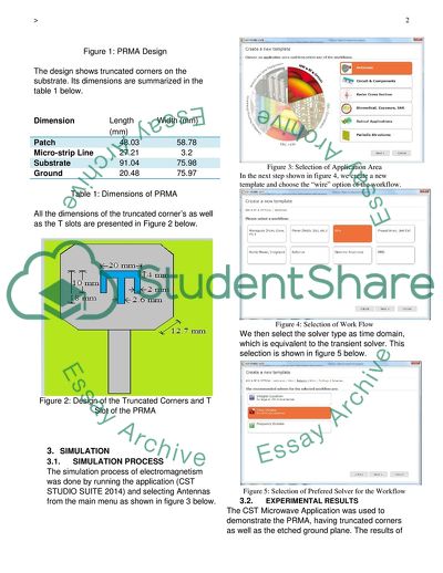
In this study, a printing and an investigation was made of the rectangular monopole antenna with an etched pulverized plane designed for a frequency range of between 1.06 and 2.17 GHz investigated. The rectangular monopole had a corner truncation placed on applied on every side as well as a T - shape slot at the center of the patch. The rectangular antenna was fabricated on its glass epoxy of the di-electric substrate. The properties of the substrate under investigation were the relative permittivity, a coefficient of 4.33, the thickness (1.67 mm). The prototype of the configuration was fixed and measured between the frequencies of 0 and 3 GHz. The simulation and the experiment outcome showed properties such as impedance bandwidth and the electromagnetic radiation. Keywords: Electromagnetism, Rectangular monopole antenna, Computer Simulation technology, band width. 1. INTRODUCTION This session introduces the application of the electromagnetism simulation tool, the CST, in electromagnetic design. The simulation is done with a rectangular monopole antenna with the feeding line and an etched ground plane having a single band antenna of frequency ranging between 1 and 2 GHz. The corners of the antenna were truncated and slotted at the center for the enhancement and optimization of its bandwidth. The PRMA (printed rectangular monopole antenna) was supplied fed by an SMA connector at 50Ω under the antenna etched ground plane (Balanis 1997, p.54). The outputs of the properties of interest from the antenna include the return loss, the patterns of radiation, the directivity and the gains as determined by the simulation process, in which this study uses the Computer Simulation Technology (CST). The PRMA is expected to be optimized in order to provide extreme wide bandwidths of the impedance, having the acceptable performance of electromagnetic radiation. The CST MICROWAVE STUDIO was the preferred software application for the simulation of electromagnetic analysis as well as the design using higher ranges of frequency range. The software applied 4 different approaches in the simulation including: Transient solver Frequency domain solver Eigen mode solver Modal analysis solver Out of the four methods, the transient solver method was the most flexible transient solver. This can obtain the whole behavior of the frequency band in a single run of calculations as opposed to the frequency stepping method of many other simulators. The solver is highly efficient in many high frequency applications including connectors, filters, transmission lines and filters. 2. ANTENNA DESIGN The PRMA antenna was designed with truncated corners located on every side of the substrate. The design is then printed with a width of 3.2 mm and a length of 27.21 mm with the feeding strip covering the substrate from one side. The design is shown in the figure 1 shown below. Figure 1: PRMA Design The design shows truncated corners on the substrate. Its dimensions are summarized in the table 1 below. Dimension Length (mm) Width (mm) Patch 48.03 58.78 Micro-strip Line 27.21 3.2 Substrate 91.04 75.98 Ground 20.48 75.97 Table 1: Dimensions of PRMA All the dimensions of the truncated corner’s as well as the T slots are presented in Figure 2 below. Figure 2: Design of the Truncated Corners and T Slot of the PRMA 3. SIMULATION 3.1. SIMULATION PROCESS The simulation process of electromagnetism was done by running the application (CST STUDIO SUITE 2014) and selecting Antennas from the main menu as shown in figure 3 below. Figure 3: Selection of Application Area In the next step shown in figure 4, we create a new template and choose the “wire” option of the workflow. Figure 4: Selection of Work Flow We then select the solver type as time domain, which is equivalent to the transient solver. This selection is shown in figure 5 below. Figure 5: Selection of Prefered Solver for the Workflow 3.2. EXPERIMENTAL RESULTS The CST Microwave Application was used to demonstrate the PRMA, having truncated corners as well as the etched ground plane. The results of the simulation are presented in figure 6 below, showing the return loss of the antenna between 0 and 3.0 GHz. It uses an SMA connector of 50Ω at port 1. The simulated PRMA maximum return loss is -21dB, which is achieved at 1.951 GHz frequency. The lower frequency (fL) is 1.071 while the higher frequency (fH) 2.175 GHz. From this we get the bandwidth of the proposed design of the antenna as 1.106 GHz. Figure 6: Simulated Result of the proposed PRMA. The dimensions of the proposed fabricared PRMA were measured using a bandwidth spectrum analyser. Figure 7 below shows the comparison of the return loss of the CST simulated outcome against the measure taken from the proposed fabricated PRMA with the use of spectrum analyser. This shows that indeed, the return loss for the fabricated PRMA design is better compared to that of the simulated results. Additionally, the fabricated bandwidth of 1.324 GHz is higher than that of the simulation for the proposed antenna, which is 1.105 GHz. Figure 7: Comparison of the simulated and Actual return loss for the proposed PRMA Antenna. The values of the feed gap were optimized to improve the bandwidth using the CST system. The different ranges of frequencies are summarized in table 2 below, showing the feed gap as a variable that depends on the frequency. Figure 8 below, shows the results of feed gap for the return loss of the proposed design of PRMA. Variation of feed gap with different lower and higher frequencies of proposed PRMA S. No. Feed Gap (mm) Simulated Frequencies Bandwidth (GHz) fL (GHz) fU (GHz) 1. 7.70 1.051 2.133 1.083 2. 6.70 1.068 2.173 1.101 3. 5.70 1.087 2.212 1.124 4. 4.70 1.103 2.256 1.152 5. 3.70 1.134 2.284 1.163 Table 2: Ranges of Frequency Figure 8: Simulated Values of Return Loss For the Proposed PRMA The second result was shown for the variation of the feed gap is because of the change in the etched ground plane length. The difference in the simulated values of lower and higher frequencies was found by varying the values of the feed gap shown in Table 3 and figure 9. They show the simulation of return losses for the proposed PRMA with the variation in the feed gap and the response and frequency bandwidth for the antenna. S. No. Feed Gap (mm) Simulated Frequencies Bandwidth (GHz) fL (GHz) fU (GHz) 1. 7.70 1.060 2.133 1.077 2. 6.70 1.068 2.175 1.105 3. 5.70 1.081 2.216 1.134 4. 4.70 1.094 2.257 1.163 5. 3.70 1.108 2.308 1.204 Table 3: The Variation of the feed gap with the difference in frequencies of proposed PRMA Figure 9: Simulation of the return loss of the proposed Antenna It is evident from the analysis of data in table 2 and table 3, that the antenna’s electromagnetic bandwidth decreases monotonically because of the increase in the lengths of the feed gap from 1.161 – 1.083 GHz in the range of 3.7 feed gap and 1.27 GHz – 1.072 GHz in the range of 7.7 mm feed gap. The variation of feed gap with for the proposed PRMA antenna bandwidth is shown in figure 10 below. Figure 10: Variation of feed gap with bandwidth of the proposed PRMA Figure 11 below shows the electromagnetic radiation pattern for the proposed PRMA antenna that has truncated corners on every corner as well as T-shaped slot at the frequency of 1.95 GHz. The electromagnetic radiation efficiency of the proposed antenna is 97.16%, the directivity of the proposed antenna is 3.809 dBi and gain of the proposed antenna is 3.684 dB. Figure 11: 3D Design of the Proposed PRMA Antenna at 1.94 GHz The directivity (dBi) of the proposed antenna and its gain (dB) is shown in the frequency range between 0 GHz and 3 GHz in figure 12 below. For the electromagnetic radiation frequencies upto 3.02 GHz, it can be observed that the antenna gain was in random increases from 1.68 to 4.64 dB. Similarly, it is seen that the directivity of the proposed PRMA antenna increases monotonically from 1.84 to 4.96 dBi as the frequency also increases. Figure 12: Directivity and Gain for the Proposed PRMA Antenna in the range 0 to 3 GHz 4. CONCLUSION Configuration of PRMA has been studied for the electromagnetic frequency band L and the difference in the improved bandwidth between the simulation and analysis is 218 MHz. After the analysis of the measured results, it is evident that increase in the bandwidth is about 218 MHz as compared to the results of the simulation in CST microwave studio. The investigation also revealed that the feed gap is dependent on the frequency and it directly affects the PRMA antenna bandwidth. The experiment successfully verifies the simulation results with good experimental agreement. 5. REFERENCES Balanis C A 1997, Antenna Theory Analysis and Design, John Wiley & Sons Inc, 2nd edition. Read More
Cite this document
  • APA
  • MLA
  • CHICAGO
(Electronic Engineering Lab Report Example | Topics and Well Written Essays - 1250 words, n.d.)
Electronic Engineering Lab Report Example | Topics and Well Written Essays - 1250 words. https://studentshare.org/engineering-and-construction/1863002-electronic-engineering-electromagnetics-module
(Electronic Engineering Lab Report Example | Topics and Well Written Essays - 1250 Words)
Electronic Engineering Lab Report Example | Topics and Well Written Essays - 1250 Words. https://studentshare.org/engineering-and-construction/1863002-electronic-engineering-electromagnetics-module.
“Electronic Engineering Lab Report Example | Topics and Well Written Essays - 1250 Words”. https://studentshare.org/engineering-and-construction/1863002-electronic-engineering-electromagnetics-module.
  • Cited: 0 times

CHECK THESE SAMPLES OF Electronic Engineering

Outline and compare frequentist view of probability and subjective view of probability

Author Name Assignment Subject Outline and Compare Frequentative and Subjective Views of Probability Introduction Probability is a subject which has found critical applications in a number of subjects.... Probabilistic studies may be required to research on a number of topics ranging from gender inequality to quantum mechanics....
5 Pages (1250 words) Essay

Project proposal

Monitoring home security and energy saving systems using smart phones Abdirahman Sultan Electrical and Electronic Engineering BSc Mohammad Masud Rana Abstract/Introduction: Monitoring home security system involves sensors that with ability to detect activities taking place around and in our homes, and additional equipment that is connected to the sensors to enable us monitor such events.... Monitoring home security and energy saving systems using smart phones Abdirahman Sultan Electrical and Electronic Engineering BSc Mohammad Masud Rana Abstract/Introduction: Monitoring home security system involves sensors that with ability to detect activities taking place around and in our homes, and additional equipment that is connected to the sensors to enable us monitor such events....
3 Pages (750 words) Assignment

The Manual for Engineers and Technicians

The manual is particularly useful to electrical and Electronic Engineering student who gets first insight on methods of repairing a mobile phone and knowledge on the internal parts of the phone.... The manual will also be used by engineering student to help them understand the electronic parts of a mobile phone.... The manual can also be used by engineering tutors to train students.... Students undertaking electrical and electronics engineering can use the manual during practical lessons....
1 Pages (250 words) Essay

Siemens Company - the Affected Shareholders

The company concentrates on developing goods for Electronic Engineering and electronic based industries.... Like the other big worldwide manufacturing companies, customers handled by Siemens Company are different governments and… In these industries, it is likely to have long term contracts with the customers that can be worth billions of dollars....
7 Pages (1750 words) Essay

Hoping to Make a Mark in Electronic Engineering

After the completion… f my degree, I hope to make a mark in Electronic Engineering and join the few individuals who have made enormous influences through innovations and discoveries in this field. Apparently, I managed to accomplish a number of things before I began my degree at ISU.... One of my Prospective Supervisor September 4, RE: MY RESUME Education I am a at ISU pursing a degree course in Electronic Engineering.... After the completion of my degree, I hope to make a mark in Electronic Engineering and join the few individuals who have made enormous influences through innovations and discoveries in this field....
2 Pages (500 words) Essay

Three-Unit Electromagnetic Generator Control

Electronic Engineering.... A DC generator produces current that flows in a constant direction as opposed to the alternating current which periodically reverses direction.... Most… The voltage regulator maintains a constant voltage level.... It achieves this through the help of a rheostat that interferes with the strength of the electric field by varying its resistance....
1 Pages (250 words) Essay

Conference Project Planning

These include the government, private and public electrical and Electronic Engineering practitioners, aspiring electrical and electronic engineers, most specifically… Like any other engineering profession, the contribution of electrical and Electronic Engineering to national economies and, by extension, the global economy, cannot be gainsaid....
5 Pages (1250 words) Essay

Professional Development as an IT Technician

In the paper “Professional Development as an IT Technician” the author discusses his experience of being a student of Electronic Engineering.... His specialist role in the construction of sweets vending machine in his group was quite an interesting role because he had the opportunity to display different skills....
6 Pages (1500 words) Assignment
sponsored ads
We use cookies to create the best experience for you. Keep on browsing if you are OK with that, or find out how to manage cookies.
Contact Us