StudentShare
Contact Us
Sign In / Sign Up for FREE
Search
Go to advanced search...
Free

Aerofoil Family for Large Blades - Assignment Example

Cite this document
Summary
The paper "Aerofoil Family for Large Blades" presents the aerofoil model - the thick aerofoil family for large blades. The tip of the blade is curved to a 95% radius. It has a primary outboard aerofoil curved to about 75% radius while the root section aerofoil curves to 40% radius…
Download full paper File format: .doc, available for editing
GRAB THE BEST PAPER94.9% of users find it useful
Aerofoil Family for Large Blades
Read Text Preview

Extract of sample "Aerofoil Family for Large Blades"

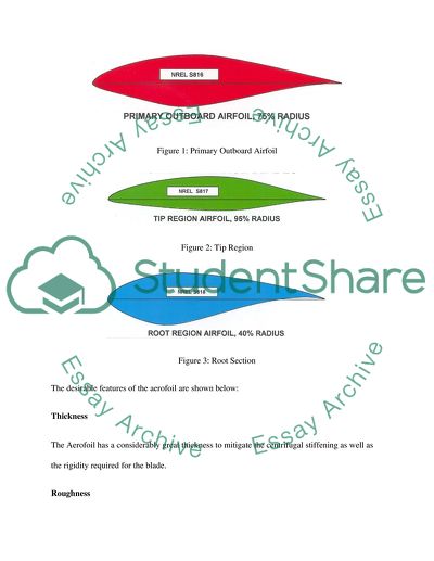
Assignment Engineering and Construction CFD (a)A of the aerofoil model you have used, including a screenshot. 10 The Aerofoil model used in this project is the thick aerofoil family for large blades. The tip of the blade is curved to 95% radius. It has a primary outboard aerofoil curved to about 75% radius while the root section aerofoil curves to 40% radius. The three sections of the aerofoil are demonstrated in figure 1, figure 2 and figure 3 below: Figure 1: Primary Outboard Airfoil Figure 2: Tip Region Figure 3: Root Section The desirable features of the aerofoil are shown below: Thickness The Aerofoil has a considerably great thickness to mitigate the centrifugal stiffening as well as the rigidity required for the blade. Roughness The aerofoil is rough enough to support the insensitivity most required for the stall - controlled wind turbines. Low Drag The aerofoil has low drag for small wind turbines. This supports the passive over speeding control as well as smaller relative control of the drag on the aircraft performance. Higher Lift Root This assists the airfoil in minimizing the consolidation of the inboard and enhances the initial torque. (b)A table summarizing any boundary conditions and constraints, with an explanation of the values selected, where appropriate. 15 The boundary conditions and constraint of the aerofoil design are summarized as shown below: Table 1: Boundary Conditions and Constraints Turbine Type Roughness Insensitive C1 Max C1 Correct Reynolds No. Thickness Low Tip C1 Max Total Improvement Stall – Regulated 10 – 15 % 3 - 5 % 10 – 15% 25 – 35% Variable – Pitch 5 – 15% 3 – 5 % 10 – 15% 8 - 20 % Variable RPM 5% 3 – 5 % 10 – 15% 8 – 10 % Explanation The Roughness insensitivity C1 and the maximum C1 ranges between 5 and 15 % for most of the vital stall controlled wind turbines. The required design of the Reynolds number is the Airfoil thickness as per the amount of centrifugal stiffening as well as the required rigidity of the blade. It ranges between 3 and 5% of the thickness. The Low drag for the small wind controlled turbines is not as essential as other factors since the passive over speeding regulates the smaller relative influences of the drag on the engine performance. The total improvement is measured by the cruise lift and the high-lift root of the airfoil to reduce the inboard solidity apart from enhancing the starting torque. The different aerofoil shapes have three possible cruise lift measures 0.1, 0.4 and 0.6. (c)Plots of the velocity and pressure profiles around the aerofoil. 20 Pressures Figure: Plotting of Aerofoil Pressure In the plot of aerofoil pressure, Cp represents the difference between LP (Local Static Pressure) and the free stream dynamic pressure. Lower Surface The lower holds the positive pressure, pulls the wing downward. In such a condition, negative Cp causes the downward pull on the lower surface closer to the mid-chord. Pressure Recovery The recovery pressure rises from the lowest minimum to the trailing edge value. This shaded region is the area of adverse gradient of pressure related to the boundary layer separation when the gradient is severe. Velocity Figure 5: Plotting of Aerofoil Velocity The velocity of the aerofoil increases with a steeper gradient from the beginning of the take-off and then the gradient gradually reduces as the aircraft stabilizes. With the airfoil positioned in the stream of air with the speed V∞, the air flow parts closer to the leading edge and then passes the upper surface and the lower surface of the airfoil at the same time. At that point, when the air flow splits up, the speed of the air flow reduces to 0, a point referred to as the point of stagnation. It is placed near the aerofoil leading edge, but the position changes in relation to the angle of attack (Bertin & Cummings 2009, p. 49). (d)A critical evaluation of the significance of the velocity and pressure profiles, with regard to how the aerofoil. 15 Pressure and Velocity have a significant effect on the performance of the aerofoil. It is found that in higher pressure zones, the velocity of the aerofoil is reduced because of strong turbulence. On the other hand, low pressure caused weak turbulence, enabling the aerofoil to experience faster cruise (Clancy 1975, p. 48). High pressure is required only in two conditions, during the takeoff and landing, where an air craft is expected to change altitude. Los speed id desired for safe landing and for climbing. The relationship between velocity and pressure is shown in figure 6 below. Figure 6: Pressure versus Velocity For the following explanations it is assumed, that a stream of air is directed against an airfoil, which is fixed in space (Houghton & Carpenter 2003, p. 83). This is equivalent to an airfoil moving through the air - just a question of the reference system. A typical wind tunnel works in the same way. Figure 7: Illustration of Pressure and velocity Figure 8 below shows the natural flow of the aerofoil without turbulence. Figure 8: Natural Airflow The qualitative performance illustrated above is referred to as the "Bernoulli effect", which is the reduction of the fluid pressure within the areas of flow as the velocity increases. The fall in pressure in the construction of the flow path is less when pressure is taken as the energy density. In the regions of higher velocity movement, the kinetic energy rises against the pressure energy. (e)The SolidWorks calculation of drag force (you should provide evidence in the form of a screenshot that you successfully implemented this). 15 Calculating the Drag Force The lift and drag have a variation in values based on the angle made by the airfoil in relation to its movement direction in a fluid. This is referred to as the angle of attack, or incident angle denoted by alpha (α) (Batchelor 1967, p. 45). In the evaluation of the airfoil, the records of lifts and drag of the airfoil are taken at different angles. The plotting of the drag force is demonstrated in figure 9 below. Figure 9: Drag Force The lift coefficient and the coefficient of drag are shown below: Lt = CL * A * qinf Dt = CD * A * qinf where: Lt represents the lift force CL represents the lift coefficient without dimensions Dt represents the drag force CD represents the drag coefficient without dimensions A represents the area of reference, or the maximum area projected on the airfoil of the plane wing qinf represents the fluid dynamic of the free stream pressure from in the Bernoullis equation: qinf = 1 / 2 rhoinf * Vinf2 where: rhoinf represents the density of the fluid in a free stream Vinf represents the speed of the fluid The area is mainly used in calculating the drag coefficient of the airfoils. The reference area for the shape being projected the plane is normal to the direction of the flow. (f)Manual calculation of the equivalent flat plate drags force.15 Numerical Calculation equivalent flat plate drags force Figure 10: Flat Plate The flat plate whose drag force is calculated is demonstrated in figure 10 above. The drag force in for the wind tunnel test is measured with the use of balances (Anderson 2007, p. 45). For the numerical methods that generates the forces at distinct positions on the mesh, the overall drag force is found by adding all the forces on the mesh elements. The forces at a mesh element are defined as: Fi = (pi * ni + taui) * Ai where: pi represents the pressure in the middle of the element taui represents the shear stress of the wall in the middle of the element Ai represents the area of the mesh element ni represents the normal direction of the mesh element i represents the element at position i Figure 11: Drag Force Illustration With the assumption of the flow as aligned with the flow direction z, the overall force is changed into the lift force and drag force elements as follows: Lt = Fy * cos(α) - Fx * sin(α) Dt = Fx * cos(α) + Fy * sin(α) where: t represents the lift force Dt represents the drag force Fx represents the drag force in direction of movement x Fy represents the force in direction of flow y α represents the angle of attack References Anderson, J D 2007, Fundamentals of Aerodynamics. McGraw-Hill. Batchelor G K 1967, An Introduction to Fluid Dynamics. Cambridge UP. pp. 467–471. Clancy LJ 1975, Aerodynamics, Sections 8.1 to 8.8, Pitman Publishing Limited, London. Houghton E L & Carpenter PW 2003, Butterworth Heinmann, ed. Aerodynamics for Engineering Students (5th ed.). p.18. Bertin JJ & Cummings R M 2009, Pearson Prentice Hall, ed. Aerodynamics for Engineers (5th ed.). p.199 Read More
Tags
Cite this document
  • APA
  • MLA
  • CHICAGO
(“CFD Assignment Example | Topics and Well Written Essays - 1250 words”, n.d.)
Retrieved from https://studentshare.org/engineering-and-construction/1694856-cfd
(CFD Assignment Example | Topics and Well Written Essays - 1250 Words)
https://studentshare.org/engineering-and-construction/1694856-cfd.
“CFD Assignment Example | Topics and Well Written Essays - 1250 Words”, n.d. https://studentshare.org/engineering-and-construction/1694856-cfd.
  • Cited: 0 times

CHECK THESE SAMPLES OF Aerofoil Family for Large Blades

Comparing Two Methods of Energy Production

The high-pressure supersaturated steam influences the blades of the turbine to react in response to the high-pressure steam.... blades are attached to the rotor that converts the steam energy into rotational motion.... The paper "Comparing Two Methods of Energy Production" focuses on the critical analysis of the comparison between conventional power generation methods and wind power generation methods the economic stability, environmental stability, and the most appropriate future power generation methods....
7 Pages (1750 words) Research Paper

Product Design of Wind Turbine Blade

Kinetic energy is formed when the blades of the turbine captures wind, making the blades rotate in its axis.... This motion of the blades creates mechanical energy that is used to generate electricity (Mahoney 1). ... A wind turbine has large rotating blades that are capable of capturing wind and creating kinetic energy.... he advantages of using HAWT are its structural stability and changeable blade pitch that allows greater control of the turbine and aids the blades in catching the maximum amount of wind....
12 Pages (3000 words) Essay

Gas Turbine Engine Compressors - Comparison

xial compressors are aerofoil based compressors utilizing rotatory movement.... It is comprised of a rotating compressor, a combustion chamber and turbine.... The compressor takes in the air at normal pressures and compresses it to higher pressures (Carl, 2002).... This paper seeks to elaborate on....
5 Pages (1250 words) Essay

Design and Evaluation of a Wind Turbine in Urban Environment

ask 3Design all the components (main shaft, blades, and tower)ITEM 3-1(blades design)blades are sensitive, and the most breakable part of the system, they are creating mechanical stress caused by centrifugal forces and fatigue, so designing the blades correctly is very important, or else they will break or not function efficiently.... TEM 3-2 (the main shaft design)The main shaft is necessary in order to assure an efficient rotation of the blades, and the blades need to rotate even when the wind is not strong, the rotor will ensure this....
21 Pages (5250 words) Assignment

Incompressible Aerodynamics

The narrator of this essay aims to tell that aerodynamics is one of the most intriguing and crucially important branches of dynamics dealing with the motion of air in relation to other moving objects.... It involves a proper understanding of the pattern of moving air.... ... ... ... This research paper is going to analyze the various aspects of the aerodynamics of an aircraft....
25 Pages (6250 words) Essay

Wind Power System for Isolated Applications

aturally, the blades interact with wind and convert wind energy into mechanical energy at the shaft.... This essay analyzes that among the possible energy sources, wind energy is one of the most promising and feasible sources in some places.... (Mutschler, 2002, 11).... Wind energy, as a renewable energy source, has the potential of being cost-effective and has a high capacity factor....
11 Pages (2750 words) Research Paper

History of Australian Aviation

Through technological advancements, aviation technology has advanced from kites, large aircraft to more sophisticated jets.... This paper "History of Australian Aviation" describes aviation in Australia, its new developments, personalities, and their achievements, and technical improvements....
8 Pages (2000 words) Essay

Aerofoils: How Wings Work

The author of the "Aerofoils: How Wings Work" paper argues that in the design of aircraft aerofoil the shape that will make the desirable lift to be achieved at a speed of aircraft that is considered as being reasonable is the most important aspect.... The effect of changing the angle of attack is clearly visualized by using the XFLR5 software The designing of the aerofoil has a major objective of ensuring there is the maximum lift is generated while lowering the amount of drag generated....
6 Pages (1500 words) Coursework
sponsored ads
We use cookies to create the best experience for you. Keep on browsing if you are OK with that, or find out how to manage cookies.
Contact Us