StudentShare
Contact Us
Sign In / Sign Up for FREE
Search
Go to advanced search...
Free

The Power Gain of an Amplifier - Coursework Example

Cite this document
Summary
"The Power Gain of an Amplifier" paper states that the common emitter configuration transistor shows the following characteristics: Low input resistance, high gain, and high output resistance hence this configuration is the best suitable for the design of amplifiers…
Download full paper File format: .doc, available for editing
GRAB THE BEST PAPER92.6% of users find it useful
The Power Gain of an Amplifier
Read Text Preview

Extract of sample "The Power Gain of an Amplifier"

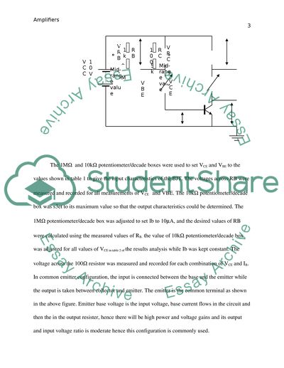
Amplifiers By Presented to September 7, Amplifiers An amplifier is a device which increases a signal power, it takes the input signal and controls the output to match the input signal but with larger amplitude. That is, the amplifier modulates the output of the power supply. Amplifiers are specified according to the properties of outputted and inputted variables, this relation of input and output properties is the gain of the amplifier and it’s given as the ratio of output voltage to the input voltage. The gain of an amplifier is given as:, voltage, current or a combination of voltage, power and current. The gain of an amplifier is usually given in decibels or its unit less if the input and output variables are the same (all current, voltage or power. The power gain of an amplifier depends on the sources and load resistances used and its voltage gain. The amplifier should be linear in most cases hence its gain should be constant. Electronic amplifiers find their applications in Radios, Television Transmitters, Receivers, and high-fidelity stereo equipments, Microcomputers, and other electronic digital equipments. METHODOLOGY AND RESULTS ANALYSIS PART A: STATIC CHARACTERISTICs OF BJTS Resistances of RC and RB were measured using an ohmmeter and the circuit below was constructed The 1M and 10k potentiometer/decade boxes were used to set VCE and VBE to the values shown in table 1 to give the input characteristics of the BJT. The voltages across RB were measured and recorded for all measurements of VCE and VBE. The 10k potentiometer/decade box was s3et to its maximum value so that the output characteristics could be determined. The 1M potentiometer/decade box was adjusted to set Ib to 10A, and the desired values of RB were calculated using the measured values of RB. the value of 10k potentiometer/decade box was adjusted for all values of VCE in table 2 of the results analysis while Ib was kept constant. The voltage across the 100 resistor was measured and recorded for each combination of VCE and IB. In common emitter configuration, the input is connected between the base and the emitter while the output is taken between collector and emitter. The emitter is the common terminal as shown in the above figure. Emitter base voltage is the input voltage, base current flows in the circuit and then the in the output resister, hence there will be high power and voltage gains and its output and input voltage ratio is moderate hence this configuration is commonly used. Table 1 Table 2 IB = 10A IB = 20A IB = 30A IB = 40A IB = 50A VCE VRC mV IC=VRC/RC VRC mV IC=VRC/RC VRC mV IC=VRC/RC VRC mV IC=VRC/RC VRC mV IC=VRC/RC 0.2V 110.369 1.103 221.698 2.217 335.551 3.356 449.509 4.496 560.20 5.602 0.4V 112.439 1.125 224.75 2.248 340.177 3.402 455.992 4.559 569.458 5.695 0.8V 112.292 1.123 224.884 2.249 340.37 3.404 456.219 4.562 569.781 5.698 1V 112.326 1.123 225.362 2.254 340.463 3.405 456.302 4.563 569.888 5.699 3V 112.645 1.126 225.777 2.258 341.368 3.414 457.545 4.575 571.507 5.715 5V 112.957 1.13 226.451 2.267 342.310 3.423 458.817 4.589 573.093 5.731 RESULTS ANALYSIS The input characteristic of the transistor was plotted as shown on the graph of IB against VBE below. The slope of the curve is the input resistance of the Bipolar Junction Transistor. INPUT CHARACTERISTIC CURVE OF A BJT AT 3V AND 5V Increasing the supply voltage causes the base current to be lower for a given value of base-emitter voltage; this implies that higher values of supply voltage leads to greater collector-base junction reverse bias, hence greater depletion region penetration into the base, thus the distance between collector-base, and emitter-base is reduced hence more charge carriers will flow from the emitter across the collector base junctions and very few charge carriers will flow out through the load at the base. A GRAPH OF IB AGAINST VBE INPUT RESISTANCE hie= VBE/ IB which the inverse of the gradient of the curve. SLOPE=13.536 Hence the input resistance of the BJT IS given as the reciprocal of 13.536 which is; hie= 0.074  From the input characteristic curve above, the value of base-emitter voltage ranges from 0.6V to 0.7V.The value of base-emitter voltage is 0.6V for small values of base current (50A or below) for higher values of base current, base-emitter voltage is 0.7v.This shows that a small increase in base-emitter current leads to a very large increase in current due to presence of low input resistance of the transistor. The input resistance varies with the value of base current flowing and below a specific value of base-emitter voltage (0.6V) the base current increases. The output characteristic of the BJT was plotted by calculating the value of collector current and plotting on the graph of collector current against collector emitter voltage for various values of base current below. Collector current varies with collector-emitter voltage for the values of collector-emitter voltage between 0V and 1V,and then it becomes constant and independent of VCE, hence the transistor is operated above 1V.In active region, collector current is small for small values of base current but the effect of collector emitter voltage on collector current increases for large values of base current. A very large value of collector-emitter voltage causes the collector-base junction to breakdown and hence the collector current increases rapidly and the transistor is destroyed. During cut-off ,small values of collector current flows even when the base current is kept at 0V.This transistor configuration is suitable for coupling between various transistor stages due to its moderate output to input impedance ratio. OUTPUT CHARACTERISTIC CURVE OF COMMON EMITTER BJT . A GRAPHN OF IC AGAINST VCE After the initial bend, the curves approximate a straight line. The gradient of each line approximates the output impedance of the BJT for a particular value of base current. The slope of the curve gives the output conductance of the BJT. The slope=1000 hence output conductance is 1000ohms.This shows that the output resistance of the transistor is high, hence from the output characteristic curves of the transistor, it is clear that for a common emitter configuration, the output resistance is high. The near horizon parts of the graph lines show that a change in the collector emitter voltage has almost no effect on the collector current in this region. This output to be expected if the transistor had a large value of resistor in series with it. The transfer characteristic curve was plotted on the graph of collector current against base current as shown below, the slope of the graph shows the current gain of the transistor. Hence from the transfer characteristic curve below, the slope is given as: Slope=0.1114, hence current gain hfe=0.1114. A TRANSFER CHARACTERISTIC CURVE OF A COMMON EMITTER BJT GRAPH OF IC AGAINST IB CONCLUSION The common emitter configuration transistor shows the following characteristics: Low input resistance, high gain, and high output resistance hence this configuration the best suitable for the design of amplifiers. Read More
Cite this document
  • APA
  • MLA
  • CHICAGO
(“Electronics Coursework Example | Topics and Well Written Essays - 2500 words”, n.d.)
Retrieved from https://studentshare.org/engineering-and-construction/1613704-electronics
(Electronics Coursework Example | Topics and Well Written Essays - 2500 Words)
https://studentshare.org/engineering-and-construction/1613704-electronics.
“Electronics Coursework Example | Topics and Well Written Essays - 2500 Words”, n.d. https://studentshare.org/engineering-and-construction/1613704-electronics.
  • Cited: 0 times

CHECK THESE SAMPLES OF The Power Gain of an Amplifier

Karaoke Type Amplifier

The circuit under discussion consists of an amplifier with 6 bands Graphic equalizer.... Circuit Operation Detailed circuit operation is given as under:- Power Supply the power supply is connected to the preamplifier and power amplifier blocks.... In the power supply, heat is dissipated during the transformer and voltage regulation stages.... From the paper "Karaoke Type amplifier" it is clear that the goal of any amplifier circuit is to reproduce the input wave shape as accurately as possible....
11 Pages (2750 words) Essay

Operating Modes and Characteristics of Operational Amplifiers

The first was not an amplifier, but a two-element vacuum-tube-based rectifier.... The first was not an amplifier, but a two-element vacuum-tube-based rectifier.... A typical operational amplifier could have a voltage gain of 200,000.... The term operational amplifier goes back to about 1943 when this name was mentioned in a paper written by john linear R.... It was in 1947 that the operational amplifier concepts were originally advanced....
9 Pages (2250 words) Essay

Feedback and Oscillators in Electronics

By and large, it increases the frequency response of any given amplifier by preventing the decrease in the gain of an amplifier.... Feedback entails this process of sending a section of the output of an amplifier back to the amplifier input.... Moreover, it limits the amplifier's input signal hence improving the fidelity of an amplifier.... During the application of an amplifier, the feedback signal reduces with the increasing input signal (Musrt, 76)....
9 Pages (2250 words) Lab Report

Circuits with Feedback and Oscillators

This paper ''Circuits with Feedback and Oscillators'' tells that The occurrence of an oscillator is such that part of the amplified signal is sent back to the input of that very amplifier (Ellinger, 2008).... This process of sending part of the amplifier output signal back to the input of is often referred to as feedback (Ellinger, 2008).... The term feedback can also refer to the process through which information on future or present events tend to affect similar events in future while a feedback amplifier is that which the fraction of output energy gets fed back to an input of that same circuit....
12 Pages (3000 words) Report

Radio Frequency Transmitters and Receivers

the power amplifier strengthens the radio frequency to enable long distance transmission through the channel.... the power amplifier strengthens the radio frequency to enable long distance transmission through the channel.... power amplification is the final stage of the radio frequency signal transmission process.... power amplification is the final stage of the radio frequency signal transmission process.... The frequency modulation signals go through the following stages: speech amplification, modulation, oscillation, frequency multiplication and power amplification....
11 Pages (2750 words) Assignment

The Use of Tuned Amplifier

From the paper "The Use of Tuned amplifier" it is clear that the high frequencies input signals to be amplified are fed to the amplifier's input.... n amplifier that amplifies a narrow band of frequencies or specific frequency is known as the tuned amplifier.... Figure 1 shows a simplified tuned amplifier circuit.... n case of signals with varied frequencies are availed at the input of the tuned amplifier, the circuit will select and then strongly amplify the signals of the resonant frequency and reject all others....
5 Pages (1250 words) Lab Report

Operational Amplifier Design

This case study "Operational amplifier Design" presents a detailed description of the design of an operational amplifier that has been set up to meet some certain specifications which are already provided.... The circuit topology of the standard operational amplifier has been chosen.... There are many challenges that are posed by the design of some amplifiers mostly due to scaling down of the channel lengths of the transistors and the supply voltages which occur at the generation stages of the operating amplifier....
8 Pages (2000 words) Case Study

Experiment Report on an Operational Amplifier

This paper "Experiment Report on an Operational amplifier" gives a basic practical summary of 741 op-amps and an opportunity to familiarize with how operation amplifiers are used as inverting amplifiers, non-inverting amplifiers, and operation amplifier adding circuit.... Op has a very high open-loop direct current gain and through applying a certain form of negative feedback an Op circuit has exact gain characteristics that are dependent only on the feedback is produced....
11 Pages (2750 words) Research Paper
sponsored ads
We use cookies to create the best experience for you. Keep on browsing if you are OK with that, or find out how to manage cookies.
Contact Us