StudentShare
Contact Us
Sign In / Sign Up for FREE
Search
Go to advanced search...
Free

Capacitance (Timing Circuits) - Essay Example

Cite this document
Summary
We can also say that it is the amount of electric potential stored for a given potential energy store in a parallel plate capacitor. Capacitance is directly proportional to the surface area…
Download full paper File format: .doc, available for editing
GRAB THE BEST PAPER94.4% of users find it useful
Capacitance (Timing Circuits)
Read Text Preview

Extract of sample "Capacitance (Timing Circuits)"

Introduction  The tendency of a capacitor to store energy in an electric field is known as Capacitance. We can also say that it is the amount of electric potential stored for a given potential energy store in a parallel plate capacitor. Capacitance is directly proportional to the surface area of the plates and inversely proportional to the separation distance between the plates in parallel plate capacitor ("Capacitance"). The formula for calculating capacitance is C=Q/VTheory CapacitanceCertain amount of energy is needed to transfer charge to the object this energy per unit of charge is called as voltage.

By providing certain voltage charge can be transferred to an object. For capacitance derived unit is useful for expressing the charge (unit of charge is Coulombs)that can be transferred to an object per unit of voltage ( unit of voltage is in Volts) and thus a unit which we got from this ratio is known as Farad. Each capacitor having two parallel plates and will have capacitance equal to 8.85 ρF/m, times the area of one of the plates, divided by the distance between them. When sharing the charge applied to one capacitor with a second capacitor, charge is conserved, therefore Vf * (C1 + C2) = Vi * C1.

When discharging a capacitor through a resistor, V(t) = V0 * e-t/RC. When charging a capacitor through a resistor, V(t) = Vf – Vf * e-t/RC (“Courseworkbank”).Timing CircuitIn timing circuits there are two possibilities either we are controlling the rate of response of the capacitor or controlling the rate of voltage across the capacitor. If a series combination of a resistor and capacitor are present such type of circuit is simplest timing circuit. The amount of time to charge the capacitor to 63% of the input voltage as well as it is equal to the resistance times the capacitance is known as time constant T=RC.

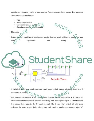
Varying the values of resistance and capacitance ultimately results in time ranging from microseconds to weeks. The important characteristics of capacitor are:ESR Insulation resistance Capacitance change vs. time Capacitance change vs. temperature DiscussionIn this section I would prefer to discuss a special diagram which will further clarify our idea about capacitance and timing circuit.A switched timer with equal make and equal space periods timing adjustable from over 6 minutes to 38 minutes.

This timer circuit is similar to the 5 to 30 minute timer except that when switch S1 is closed, the on/off action of the circuit will continue indefinitely until S1 is opened again. A 7555 time and low leakage type capacitor for C1 must be used. The 6 way rotary switch S3 adds extra resistance in series to the timing chain with each rotation, minimum resistance point "a" maximum point "f". The 7555 is wired as an equal mark/space ratio oscillator, the timing resistor chain R1 to R6, being connected back to the output of the timer at pin 3.

The output pulse duration is defined as:-T = 1.4 R1 C1This gives on and off times of about 379 seconds for position "a" of S3 (just over 6 minutes), to about 38 minutes at point "f". The times may of course be varied by altering R1 to R6 or C1.ConclusionCapacitance can be defined as the tendency of a capacitor to store energy in an electric field. The formula for calculating capacitance is C=Q/VThe unit of capacitance can be derived from the above formulaCapacitance= Coulombs(Unit of charge) Volts(unit of voltage)Therefore, the derived unit of capacitance is Farad.

In timing circuits when a capacitor is charged through a resistor then the voltage equation is given byV(t) = V0 * e-t/RC.Where V0 is initial voltage Similarly, when a capacitor is charged through a resistor then the voltage equation is given by V(t) = Vf – Vf * e-t/RC.The timing constant of a timing circuit is given by the equationT=RCWhen the value of resistance of capacitance is changed then the time can change from microseconds to weeks. Therefore, this timing constant plays an important role in the timing circuit.

References1. "Capacitance." Capacitance. N.p., 6 Sep 2011. Web. 12 Sep 2011. .2. "Capacitance." Courseworkbank. N.p., n.d. Web. 12 Sep 2011. .

Read More
Cite this document
  • APA
  • MLA
  • CHICAGO
(“Capacitance (Timing Circuits) Essay Example | Topics and Well Written Essays - 500 words”, n.d.)
Capacitance (Timing Circuits) Essay Example | Topics and Well Written Essays - 500 words. Retrieved from https://studentshare.org/engineering-and-construction/1579935-capacitance-timing-circuits
(Capacitance (Timing Circuits) Essay Example | Topics and Well Written Essays - 500 Words)
Capacitance (Timing Circuits) Essay Example | Topics and Well Written Essays - 500 Words. https://studentshare.org/engineering-and-construction/1579935-capacitance-timing-circuits.
“Capacitance (Timing Circuits) Essay Example | Topics and Well Written Essays - 500 Words”, n.d. https://studentshare.org/engineering-and-construction/1579935-capacitance-timing-circuits.
  • Cited: 0 times

CHECK THESE SAMPLES OF Capacitance (Timing Circuits)

Low power reduction Electrical Engineering

hellip; Until the invention of the silicon integrated circuit in 1958, however, semiconductor devices existed as discrete devices and circuits were not particularly low in power consumption compared to to-day's circuits, but much lower than vacuum tube circuits.... Integrated circuits (ICs) reduced power consumption further, because numerous devices could be placed on one chip, alleviating the interconnect problem and reducing power consumption....
12 Pages (3000 words) Essay

Thyristor or Silicon Controlled Rectifiers

The DV / DT creates a displacement current in the depletion layer capacitance of the middle junction, which induces emitter current in the component transistors and causes switching action (Dorf, 1997).... This paper ''Chopper Control'' tells that There are two forms of electrical energy supplies namely, AC and DC....
12 Pages (3000 words) Essay

Analog Circuit Computer Aided Design (CAD)

Basic problem with that approach is that super circuits must be worked out for each sort of analog cells.... The main purpose of this research of “Analog Circuit Computer Aided Design” is to get the values of transistor sizes and components values like resistors and capacitances if the analog circuit specification is given....
4 Pages (1000 words) Essay

Radio Frequency Transmitters and Receivers

The carrier frequency that is intended to be used is normally generated using crystal oscillator circuitry/ capacitance inductance based Variable Frequency Oscillator.... This paper highlights that There are a number of stages involved in the transmission of Amplitude modulated signals or radio frequencies....
6 Pages (1500 words) Assignment

Designing and Testing of a Delay Unit

The outputs from these comparators normally control the internally built flip flop circuits that toggle 555 timer's output, then, adjusting the control voltage at pin five varies the frequency at which the 555 timer's output is toggled at.... nbsp;An astable multivibrator can be defined as a timing circuit with an output that oscillates between the logics low and high without stopping, as a result, it creates a full train of pulses....
5 Pages (1250 words) Lab Report

Design and Testing of a Delay Unit: Voltage Controlled Oscillator

The in-built flip-flop circuits are usually controlled by the outputs received from these comparators, as these circuits toggle the output of the 555 timers.... nbsp;A stable multi-vibrator is a timing circuit that has an output of constant oscillation, between the given logic of high and low, without any stopping in between....
6 Pages (1500 words) Lab Report

Designing and Testing of a Delay Unit

The outputs from these comparators usually control the internally constructed flip flop circuits that toggle 555 timer's output, then, regulating the control voltage at pin 5 varies the frequency at which the 555 timer's output is changed at.... nbsp;A stable multi-vibrator can be described as a timing circuit with an output that oscillates between the logics low and high continuously, as a result, it creates a full train of pulses....
5 Pages (1250 words) Lab Report
sponsored ads
We use cookies to create the best experience for you. Keep on browsing if you are OK with that, or find out how to manage cookies.
Contact Us