StudentShare
Contact Us
Sign In / Sign Up for FREE
Search
Go to advanced search...
Free

Radio Frequency Transmitters and Receivers - Assignment Example

Cite this document
Summary
This paper highlights that There are a number of stages involved in the transmission of Amplitude modulated signals or radio frequencies. The carrier frequency that is intended to be used is normally generated using crystal oscillator circuitry/ capacitance inductance based Variable Frequency Oscillator…
Download full paper File format: .doc, available for editing
GRAB THE BEST PAPER98.2% of users find it useful
Radio Frequency Transmitters and Receivers
Read Text Preview

Extract of sample "Radio Frequency Transmitters and Receivers"

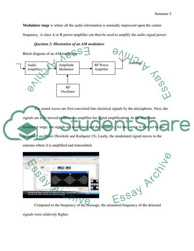
Task 1 Question 1: Radio Frequency System of an Amplitude Modulated Transmitter There are a number of stages involved in the transmission of Amplitude modulated (AM) signals or radio frequencies. At the first stage (RF Oscillator stage), the carrier frequency that is intended to be used is normally generated using crystal oscillator circuitry/ capacitance inductance based Variable Frequency Oscillator (VFO). Next, the low power RF carrier output of the RF oscillator is then taken to the buffer amplifier stage where the output impedance of the carrier oscillator is marched with the input impedance of the frequency multiplier before they are isolated (Carr 44). At the Frequency Multiplier stage, higher harmonics of the carrier oscillator frequency are generated and the signals then move to the Power amplifier stage for amplification. On the other hand, the chain of the audio signal that is intended to be transmitted begins from the microphone and is then moved to the audio driver amplifier where the voltage of the signal is amplified in order to drive the audio power amplifier. As indicated in the block diagram, the Modulator stage is where all the audio information is normally impressed upon the carrier frequency. A class A or B power amplifier can then be used to amplify the audio signal power. Question 2: Illustration of an AM modulator Block diagram of an AM modulator Antenna The sound waves are first converted into electrical signals by the microphone. Next, the signals are then moved to the audio amplifier for signal amplification. At the amplitude modulator stage, the signals are modulated and the frequency for the carrier is then set by the frequency oscillator (Newkirk and Karlquist 15). Lastly, the modulated signal moves to the antenna where it is amplified and transmitted. Compared to the frequency of the massage, the measured frequency of the detected signals were relatively higher. Question 3: Single Sideband Amplitude Modulation In order to determine the lower side band at the output, the frequencies of the double sideband full carrier (DSBFC) spectrum presented above can be calculated by using a mathematical formulation: Lower sideband = Carrier frequency - modulating frequency  = fc-fm = 10 kHz 150 kHz = -140 kHz The lower side band at the output= 140 kHz Task 2 Question 1: Frequency-Modulated Transmitter In the frequency modulated transmitters, the modulating signals normally combine with the carrier to cause the variation of the frequency of the resultant wave with instantaneous amplitude of the modulating signal. In the first stage, the audio signals are amplified before they are moved to the modulator. The amplifier particularly converts the low power input audio signals into higher power signals while at the same time preserving the frequency and amplitude of the input signals. At the modulator, modulating audio signals are applied to a varicap diode thereby making the reactance to vary around the center frequency. This consequently changes the frequency of the oscillator in line with the modulation thereby providing Frequency modulation. After modulation, the signals move to the Oscillator stage where a stable sine wave signal is generated at the rest frequency but no modulation is applied. In the next stage, the oscillator output is fed to the frequency multiplier. This stage features a number of frequency multipliers which performs frequency multiplidation in order to increase the frequency of the modulated signals. Finally, after the multiplication of the frequency, the signals move to the power amplifier stage where the amplitude is increased to the required level for transmission. Just like in the AM transmitters, the impedance matching network then matches the antenna impedance to the correct load over the amplifier. Question 2: Angle modulation When the modulation index was changed to ᵝ=2 and ᵝ=8, a number of changes were observed in the FM output. For example, there was brighter sound when the modulation was changed to ᵝ=2 as the higher ß resulted in a broader series of sidebands and a significantly more complex spectrum in the FM output thereby leading to a brighter sound. On the other hand, changing the modulation index to ᵝ=8 resulted in more noise at the FM output since the modulation index was exceedingly high. The resulting changes observed in the FM output when the modulation index was changed to ᵝ=2 and ᵝ=8 are attributed to the fact that in any given audio-frequency (FM), modulation index( ß) is defined as the ration of carrier that deviates from the unmodulated frequency divided by the modulator frequency. ß = (Dfc-pk) / fm. It can therefore be argued that the Modulation Index determines the amplitude of the spectrum components of the FM output signal. Task 3 AM tuned-radio frequency (TRF) receiver Antenna Output A tuned radio frequency receiver refers to a radio receiver which is often composed of a number of multiple tuned radio frequency amplifiers which are followed by circuits for purposes of detection and amplification of the audio signal (Carr 168).The above shown block diagram divides the T.R.F receivers into three major sections. The first section is the RF section which contains a single, double or three stages of R.F amplification. The tuning of the receiver will often take place at this stage. Coming after the R.F amplifiers is the detector. At this section, an A.F component is split from an R.F portion of a carrier wave. The A.F wave is then sent on to the third section of the audio frequency amplifier where additional amplification occurs. The last procedure gets accomplished if the audio signal eventually appears within loudspeakers or ears phones as sound. Each tuned RF stage constitutes an amplifying device alongside a tuned circuit which carries out filtering. In a classic TRF receiver of the 1920s, an amplifier would be a triode vacuum tube. Found in every pair of stage was some air-core RF coupling transformer which helped in coupling a signal from a plane circuit of a given tube to the input grid circuit of the tube that followed. Task 4 Principle of Operation of the Superheterodyne Receiver The superheterodyne receiver constitutes all the main components of the T.R.F alongside three additions. Signals will enter a front end circuitry from the antenna. The front end amplifier and tuning block is charged with two roles. First, it applies broadband tuning to the RF stage, a move that is aimed at accepting signals on the wanted frequency while rejecting those on an image frequency. Second, it sufficiently amplifies signals while aiming at achieving a proper signal to noise ratio. At the mixer, a signal that is tuned and amplified will enter a single port of the mixer while a local oscillator signal gets into the other port. At this stage, mixer performance remains crucial in view of the general performance of the receiver (Sharma 372). At the local oscillator, there might be a variable frequency oscillator which could be tuned through alteration of the setting on variable capacitors. After a signal leaves a mixer, it enters the IF stages. The stages have majority of amplification inside the receiver plus the filtering which makes it possible to differentiate signals based on frequencies. After passing through the IF stages, there arises a need to have signals demodulated. This achieved at the demodulator stage. The kind of demodulator used is dependent on the transmission type. Out of the demodulator comes a recovered audio as an output. This will be passed to the audio stages during which they will be amplified then presented to the loudspeakers or headphones. Task 5 The necessary Arrangements for Transceiver Operation In order to overcome some of the difficulties that when both a transmitter and a receiver are joined together in one circuit board to obtain a transceiver, a special kind of arrangement is normally needed to ensure that the transceiver is able to operate effectively. The necessary arrangement normally involves the use of single aerial antenna in order to protect the receiver section. This can be particularly achieved by placing a pair of opposed diodes from the receiver input to the ground to ensure that the transceiver is able to safely pass potential excess voltages to the ground. For example, the necessary arrangement can be achieved using the antenna relay by ensuring that any time the transmit button is pushed; the relay pulls in thereby removing the antenna from the receiver and connecting it to the transmitter. On the other hand, another pair of contacts should also be used to connect the receiver input to a grounded outlet. In addition, pin diodes are can provide an important alternative to relay since they operate faster and can be connected in series to provide extra attenuation of the signals moving to the receiver. Generally, this kind of arrangement will present an open circuit to the signal voltages while at the same time clamping excess voltages from their forward bias voltages. The additional front end protection offered by the arrangement not only protects the operations of the transceiver but also ensures operation within the required voltage ranges. This is critically important because transmitters normally generate excess voltage that is sufficient enough to interfere with the operations of the receiver by destroying the first amplifier of the receiver when it is joined together with the transmitter. Works Cited Carr, Joseph J. Practical Radio Frequency Test and Measurement: A Technician's Handbook. Boston: Newnes, 1999.Web. 12 Jun. 2014. Sharma, S.P. Basic Radio and Television. New Delhi: Tata McGraw-Hill, 2003. Print. A.P.Godse and Bakshi U.A. Communication Engineering. London: Technical Publications.2009. Print. p. 36 Newkirk, David and Karlquist, Rick. Mixers, modulators and demodulators: The ARRL Handbook for Radio Communications. Newington: ARRL. 2004. Print. , pp. 15.1–15.36. Read More
Cite this document
  • APA
  • MLA
  • CHICAGO
(Radio Frequency Transmitters and Receivers Assignment - 1, n.d.)
Radio Frequency Transmitters and Receivers Assignment - 1. Retrieved from https://studentshare.org/social-science/1831425-radio-frequency-transmitters-and-receivers
(Radio Frequency Transmitters and Receivers Assignment - 1)
Radio Frequency Transmitters and Receivers Assignment - 1. https://studentshare.org/social-science/1831425-radio-frequency-transmitters-and-receivers.
“Radio Frequency Transmitters and Receivers Assignment - 1”, n.d. https://studentshare.org/social-science/1831425-radio-frequency-transmitters-and-receivers.
  • Cited: 0 times

CHECK THESE SAMPLES OF Radio Frequency Transmitters and Receivers

Super Heterodyne Receiver

Commercial production of super heterodyne receivers by the mid-1930s largely replaced the production and use of preceding receivers designs specifically tuned radio frequency receivers.... All modern television and radio receivers virtually use the principle of super heterodyne.... These amplifiers were used in equipment for radio direction finding and Armstrong realized that if these receivers could be operated at a much higher frequency, they would be better and more effective....
4 Pages (1000 words) Essay

AM Transmitter Circuit

AM transmitters and receivers.... The term Amplitude Modulation (AM) refers to the type of modulation in which an audio signal is combined with a radio frequency carrier in such a way that total wave power is made to vary in accordance with the modulating audio signal (Bertrand 1).... … AM Transmitter The term Amplitude Modulation (AM) refers to the type of modulation in which an audio signal is combined with a radio frequency carrier in such a way that total wave power is made to vary in accordance with the modulating audio signal (Bertrand 1)....
2 Pages (500 words) Assignment

Code Division Multiple Access

The waves are generated by the transmitter at the same frequency, and then each of the components is modulated by 0 or 180 degrees phase shifting (detecting 180 degrees phase shifts is easier than detecting 90 degrees phase shifts).... Code Division Multiple Access is a form of Direct Sequence Spread Spectrum communications where the channel resources are shared by all the service users....
4 Pages (1000 words) Assignment

Homodyne Receivers

A homodyne receiver is a particular architectural design of a wireless radio frequency (RF) receiver.... he functionality of homodyne receiver is Homodyne receivers The homodyne architecture once overwhelmed by the more complex heterodyne architecture came back to utility as the performance and functionality requirements for many newer applications were demanding such a design.... ource: (Ma,2008)Advantages of Homodyne receiver The simplicity in its constitution and function is the prime advantage of this type of receivers....
1 Pages (250 words) Essay

REPORT ON AM TRANSMISSION AND RECEPTION

Modulation is an important technique to transmit signals through high frequency carrier wave, as it requires small amount of power with nominal size antenna to transmit and receive signals over air waves.... Also there is very slight interference among TV, radio and cellphone… In AM, the amplitude of the sinusoidal carrier wave is changed with the message signal while frequency and phase remain constant.... Before mixing the signal to local tune, the received signal efficiency is enhanced through a RF amplifier and then shifted to pre-define IF frequency, normally at 455 KHz in AM broadcasting systems....
5 Pages (1250 words) Essay

The History of Police Scanners

As early as the beginning of the 20th century, military and naval warships were applying the 2-way form of communication through the installation of both transmitters and receivers in the ships.... The idea of using receivers and transmitters began in the early 20th century where 2-way telegraphy traffic was in commercial use in the Atlantic Ocean.... According to Scanner Master, police departments implemented the aid of tunable radio receivers to monitor police channels using a low frequency at the receiving end of the AM radio dial around 1700 KHz....
4 Pages (1000 words) Essay

Critical Process Paper

At this stage, the transmission is done in one way only to ensure all the information fed into the AM is compatible with envelope detector receivers.... During this stage, both the phase and the mixed audio signals are modulated to avoid interfering with the envelope detector receivers.... n the second stage of transmission of data, the conventional AM mono transmitters are replaced with a stereo mixed audio input.... The main focus of the paper "Critical Process Paper"  is on examining such aspect as new radio technologies and their advantages, digital audio broadcasting, HD radio, digital radio Mondiale, manufacturers, radio industry, various challenges, listeners, traffic announcements....
6 Pages (1500 words) Essay

How Superhet Principle Leads to the Production of Selectivity in Receivers between the Signals

Question 2Discussion on how the superhet principle leads to production of adequate selectivity in radio receivers between the signals.... … Part 1: Section CQuestion 1From the output wave form obtained from the linear modulator, its spectrum diagram is obtained as follows;The carrier frequency of the signal is obtained as;The amplitude of the spectrum is obtained by equating its Part 1: Section CQuestion 1From the output wave form obtained from the linear modulator, its spectrum diagram is obtained as follows;The carrier frequency of the signal is obtained as;The amplitude of the spectrum is obtained by equating its amplitude to half of that of the carrier signal....
3 Pages (750 words) Assignment
sponsored ads
We use cookies to create the best experience for you. Keep on browsing if you are OK with that, or find out how to manage cookies.
Contact Us