StudentShare
Contact Us
Sign In / Sign Up for FREE
Search
Go to advanced search...
Free

Design of Solar Boat for Competition - Case Study Example

Cite this document
Summary
The paper "Design of Solar Boat for Competition" states that using the baffled boat as the base design, the scaled-down prototype will be utilized for testing various components for motor efficiency, structural integrity, and the length of charge of the solar panels…
Download full paper File format: .doc, available for editing
GRAB THE BEST PAPER91.2% of users find it useful
Design of Solar Boat for Competition
Read Text Preview

Extract of sample "Design of Solar Boat for Competition"

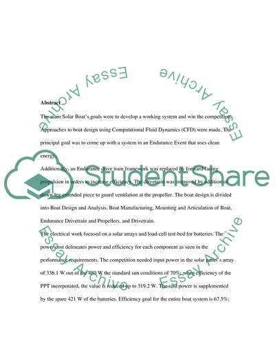
SOLAR BOAT Table of Contents 3 INTRODUCTION 5 1 Definition of Need 5 2 Proposed Market 5 3 Previous Designs 6 4 Design Objectives 7 1.4.1 Performance Specifications 8 1.4.2 Design Process 9 2.CONCEPT GENERATION 11 2.1 Alternate Concepts 11 2.1.1 Design One 11 2.1.2 Design Two 12 2.1.3 Design Three 12 2.1.4 Alpha Prototype 12 2.1.5 Beta Prototype 13 2.1.6 Beta Plus 13 3.FUNCTIONAL ANALYSIS 17 3.1 Design Optimization 18 3.2 Engineering Analysis 22 3.2.1 Structural Analysis 29 4.ECONOMIC ANALYSIS AND BUSINESS PLAN 32 5.NEXT STEPS 34 APPENDIX A: CITATIONS 35 Abstract The main Solar Boat’s goals were to develop a working system and win the competition. Approaches to boat design using Computational Fluid Dynamics (CFD) were made. The principal goal was to come up with a system in an Endurance Event that uses clean energy. Additionally, an Endurance drive train framework was replaced by forward-facing propulsion in orders to increase efficiency. The drivetrain was improved by addition of down-leg extended piece to guard ventilation at the propeller. The boat design is divided into Boat Design and Analysis, Boat Manufacturing, Mounting and Articulation of Boat, Endurance Drivetrain and Propellers, and Drivetrain. The electrical work focused on a solar arrays and load-cell test-bed for batteries. The power cost delineates power and efficiency for each component as seen in the performance requirements. The competition needed input power in the solar panel’s array of 336.1 W out of the 480 W the standard sun conditions of 70%; when efficiency of the PPT incorporated, the value is reduced up to 319.2 W. The said power is supplemented by the spare 421 W of the batteries. Efficiency goal for the entire boat system is 67.5%; sum of efficiencies of the motor, controls, propeller, and gearbox. Hence results in, output power of500 W, and 132 N of thrust, when at a speed of 13.7 km/hr. Continuous usage of fossil fuel, as the principal source of energy, is harmful towards the environment and ecosystem. Therefore, it is inevitable to look for and utilize both environmentally and eco-friendlily machines or objects that utilize renewable or the ‘alternative’ source of energy. The objective of this project is to design, modify and create an environmentally and eco-friendly boat that will be used for racing. The concepts of renewable energy usage as the primary source of energy were addressed on the environmental impact; the boat designs and modifications and propulsions were considered in the conservation of ecosystem. The major issues with boat building is the standards (or racing) requirements and regulations, for example, one foot clearance depth for boat hull in order to protect the seabed in low tides. A successful outcome has been achieved due to the optimal combination of materials, hull type and choice of boat, and propulsion system adhering to regulations; in additional to that, functional and attraction feature have been met. Three conceptual designs dedicated to the hull was to be chosen, the promising one has been selected in redesigning of an eco-friendly boat. 1. INTRODUCTION 1.1 Definition of Need Mechanical engineering students at Imperial College, London, United Kingdom participated in an all solar powered boat racing competition, but most of the undergraduate students did not reach the finishing line, and there were low speed recorded (Weston, 2008). The main purpose for the design project is to redesigning an eco-friendly racing boat that is fast, looks elegant and efficient in performance. 1.2 Proposed Market The solar powered boat will target the European, North American and Asian markets; specifically Canada, Britain, and Qatar. In these countries, owners of solar boats are less than 10 percent. These countries boast of high-income per citizen. Figure 1: Major Owners of Solar Powered Boats in the World The proposed markets targets 70,000 solar boat enthusiasts (an average of 23,333 people per country), in Canada, Britain, and Qatar. This is estimated from the survey of 2013. Qatar holds the largest market share of solar boat enthusiasts, from native and tourists, at 28,000 people; Canada at 24,500 people and then Britain at 17,500. Each unit will be at $ 6,000, and a predicted profit of $18 million should be achieved by the end of four years. 1.3 Previous Designs The solar Boat Company is one of the leading manufacturers of the Electric powered boats (Solar Boat Co, 2014). The boat manufacturer has gone to the extent of producing electric propulsion frameworks on the canal boats. They have also designed cruising burges purely on solar power. Advantage of the Solar Boat Products: Their systems are eco-friendly since they discourage internal combustion; also the solar panel helps a lot in saving the fuel costs. From their calculations they estimated that every 100 watt per solar energy saves over 55 liter of fuel in a year (Solar Boat Co, 2014). Figure 2: Solaris Cruiser; has twin hull (http://www.solarboat.co.uk/gallery.shtml) Disadvantages of the Solar Boat Products Most of their work is based on replacement of the internal combustion systems and not the whole system analysis; hence efficiency is scarified. There boats are slow and could save even more fuel if they considered analysis their systems and components before implementing. 1.4 Design Objectives Achieving the design requirements of flotation calculations, proof of insurance, and boat batteries Hydrofoil Design: Design hydrofoils for competition using analytical tools such as computational fluid dynamic (CFD) in predicting lift and drag Hydrofoil Manufacturing: Select material that is inexpensive and easy to machine and be easily infused into carbon hydrofoils for good surface finish and precise foil profile. Articulation and Mounting of Hydrofoils: Vary the extent of lift from the hydrofoil with surface piercing idea since this configuration is inherently stable; many power boating teams use it. Endurance Drivetrain: Develop a custom drivetrain and motor for the competition’s Endurance Test. The submerged pod housing the motor with a 5:1 gearbox attached to the propeller; proper drivetrain reduce losses and it will be useful in the competitions Drivetrain: The high-efficiency motors will be incorporated with drivetrain that has new down-leg. 1.4.1 Performance Specifications To meet racing goals the following requirements must be met; usually by the use of weight budgets and the power for each structural component in the boat. They include: • Endurance Event setting of hydrofoils should lift force of 294 kg, to driver and lift boat such that the boat’s hull is wholly out of water; and at a speed of 13.7 km/hr. The integrated weight of the back and front hydrofoils should not exceed weight of 111. The variable lifting mechanism should maintain the lift in the course of racing and the incorporated weight of the whole mounting and articulation system must not exceed 89 N The weight of the drivetrain should be less than the 120 N The improved podded propeller should be able to decrease drag by 3 percent of whole boat drag 1.4.2 Design Process The racing boat will combine the design methodologies in order to win the race. A standard race event requires the following considerations in terms performances (100 meters): First competition in the event to be completed in less than 43 seconds Second competition in the event to be completed in less than 40 seconds Third competition in the event to be completed in less than 26 seconds, at 46.7 km/hr. Maintaining an average speed of about 13.7 km/hr in the Endurance Race Event The overall performance requirements and the anticipated sun conditions, led to the development of a power budget used in the Endurance Event as shown in Table 1. Table 1: The Power Budget for Endurance Event The power budgets are useful in tracking the amount of power required or consumed by the system via components of the solar boat; based on efficiencies and performance characteristics. The power budget is essential when it comes to dictating an individual component’s performance specifications. Mostly in the power budget, the values imply to output values quantity for every component and the input values for down streaming components (Patel, 2012). A second design comes from Table 1, hence called weight budget as seen in Table 2. Table 2: Weight Budget for Endurance Event 2. CONCEPT GENERATION 2.1 Alternate Concepts 2.1.1 Design One Flat bottom boats are ideal in areas the area of shallow bodies of water. The Hull’s shape enables the boat to maneuver on top of the water contrary, instead, of through ways. This characteristic gives the boat the wanted stables design. In addition, the flat bottom hulls avail greater buoyancy. Hence, boats of this nature have a tendency having very high decks thus making the rides dry. This particular design allows smooth ride especially in calm waters; on the contrary, the choppier waters lead to rides that are rougher. Another drawback is that flat bottomed boats not maneuverable as compared to other hull types. The intent this project is the calmer waters, moderate horsepower motors are required. In case the powers are great, then roughness of the ride will be increased. 2.1.2 Design Two The round bottomed hull resembles the flat bottom; they are used at moderate speeds, and calm waters. The food for thought is why it is different. The round bottomed boats are displacement type hull hence contrary to the planning of the hull; flat bottom. A displacement hull maneuvers via the water instead of on top of water. This shape additionally, gives the vessels greater maneuverability. 2.1.3 Design Three The final design option that is being looked at is that of the racing solar boat. Similarly, like the round bottom hull, the racing boat is a displacement hull type. This hull type shape avails for enough deck area, if the boat is to accommodate batteries, solar panels, passengers, and other components. The only disadvantage of this design shape is that the efficiency is compromised. 2.1.4 Alpha Prototype The material required for the hull construction is a vital factor that is considered. Series of studies will be carried in consideration of all materials characteristics; selecting the best material for the application design could be beneficial. There are selective options in the market for fiberglass, aluminum, carbon fiber or Kevlar, and wood. Hence aluminum, being less affordable, is an ideal candidate for racing boats. Fiberglass, possess lightweight and durability characteristic, and long lifespan, hence one of the first choice for racing boat builders. Kevlar or Carbon fiber is applied in many companies it is costly. Wood, is worthy when successfully designed. The new composites are desirable; have the required properties, in making the construction cost efficient and lighter. 2.1.5 Beta Prototype The principal objective behind the project is to rebuild a racing boat that is eco-friendly. After analyzing many boats’ designs; and taking into consideration the study in conjunction with building analysis of the boats’ parts, a racing boats’ hull is the best choice. To start, due it is very simple to design, a racing boat is raised deck that will be held by outer bracing. Solar panels will be place on the overhead area, hence will still work in sun shelter and provide the required power for the traction of the electric motor. A hybrid system is intended with combination electrical energies received from solar panels while other availed from the regular power source. The system will utilize a power system that utilizes battery inverters with battery banks that store electricity prepared for later use. Since batteries are incorporate in the system, the solar charge controller is required for charging the battery bank hence preventing over charging. 2.1.6 Beta Plus Hydrofoil Design: A racing boat with hydrofoils will be faster than normal boat since the foils in flying speed, lifts the boat out of, the water, hence reducing the drag force exerted at that speed. Forces acting upon the hydrofoil are similar to that of airplane wings. The only difference is theory is evidence of free-surface interface above the hydrofoil. Two major types of hydrofoils are submerged and surface piercing hydrofoils, Figure. Surface piercing hydrofoils are simple to design or implement since they self-stabilize and also control lift; the draw that they have is that they are less efficient due to the lift force acting at angles. Submerged foils are not self-stabilizing but efficient. Figure 3: Fully submerged and Surface piercing foils. Hydrofoil setup depends on the size of aft and the forward foils; whether or not “split” individual hydrofoil. In standard configurations, front foils help in supporting 65% of the boat’s weight, will the rear one support the major weight. CFD is used in fluids in motion calculation via physical characteristics of their differential equations. CFD can predict the design performance before implementation. Hydrofoil Manufacturing: The first foils are constructed with wood core blende with fiberglass for extra strength. Mounting and Articulation of Hydrofoil: This is vital in the design. Without any variance in lifts, hydrofoils are evidently dynamically unstable. They will not fly at constant clearance above the water’s surface instead on a positive feedback loop. But when lift is increased from heightened speed they bow gains in clearance and increases the angle-of-attack. Endurance Drivetrain: Solar boat will utilize the backward faced podded propellers as in the shown Figure .Streamlining will be considered in inline motor, propeller, and gearbox. The inline design is a combination a gearbox efficiency with 95%, minimizing losses in the drive system. Figure 4: Podded Propeller Figure 5: Implementation of the Extension Piece Sectional View Sprint Drivetrain: The easiest way of eliminating propeller ventilation dropping the propeller deeper into the water via the lengthening of its down shaft. The extension can be accomplished via the current transition piece or an extra extension assembled in either the transitional piece or the lower gear units. Figure 6. Load-Cell Testing Load-Cell Test-Bed: This is the tool utilized in characterizing solar panels or batteries. Solar Array: implemented via test-bed; hence 4 panels of about 4in x 4in cells connected. 3. FUNCTIONAL ANALYSIS The Archimedes’ principle is the physical law which will establish if the boat will be partially or totally immersed in water; it states that an object (boat) is to experience an upward force/thrust that is equal to the weight of water (liquid) it displaces. This law will help determine if the boat will float or sink. The key “boat” concept the principle is thrust; the force acting up hence reducing the weight of the boat in water. If the boat’s average density is less than that of water, then it will float. If the power boat is completely submerged in water, then the weight of water displaced greater than that of its weight, and power boat is driven up and hence out of the water until weight of displaced water due to the submerged section is precisely equal to the weight of the floating solar boat. weigh – weigh of displaced fluid = Apparent immersed weight = = For example, if the solar boat is 1/6 of the water, it will float with 1/6 dipped volume in water, since the weight, mainly, of displaced water is equal to the boat’s weight. This principle proves on why big ships and huge boats do not sink. Any regular boat floats lower in water when loaded heavily since water is required to be removed in order to generate forces necessary for floating. In addition, similar sized ship in salty water is heavily loaded as compared to when in fresh water, since fresh water is less dense as compared to salty water. 3.1 Design Optimization Single 3D Foil Flow: Wingtip vortices are main sources of drag, it is necessary to explore. Figure 7: Flowchart with models stating purpose Figure 8: C-grid Mesh for the Clark Y airfoil Figure 8 B: Rear and Front foils as used in design. Figure 9: Percentage of the coefficient of lift with drag changes when compared in 2D Figure 10: Wingtips vortex streamlines coming from a 3D wing that has a square winglet when simulated at the velocity of 8.5 mph (0.74 taper wings and 11.8 aspect ratio). The colouring corresponds to various velocity magnitudes. Figure 11: Percentage change in CD and CL for 3D wings having 0.74 and 11.8 AR taper 3.2 Engineering Analysis Solar powered boats generally have many different parts. Most the parts depend on the size and type of boat. The major components of the solar boat for competition are the hull, keel and propeller. Figure 12 a: Boat Components Figure 12 b: Boat Components Hull The hull is considered one of important components to be designed in this power boat; this is the waterproof body section of the boat. Decks, engines, mast and rudders are inclusively installed at the hull. The part changes with respect to vessel type. Hulls are built as smooth curved, hard chined or chined hull. Smooth Curve Hull The Curved hull is rounded and made not to have corners. This hull is the most common one since it enhances planning. Figure 13: Smooth Curve Hull Chined and the Hard Chined Hulls Chine in the boating language is the sharp angle found in the hull. The hard chine has angle with little rounding, while soft chine is more rounded Figure 14: A. An S Bottom Hull ; B. The Hard Chine, and C. The Soft Chine Propeller This is included in the priority list of major components of the solar powered boat. The propeller will be utilized in the transmission of power via rotational transformation of motion into thrust. During rotation, forces created via rotation are converted into pressure, hence accelerating the solar boat backwards or forward. Most propellers’ axis is parallel to that of the fluid flow. Controllable pitch, modular and skewback are the different types of propellers. Controllable Pitch Propeller This propeller is advantageous to ships, since it has the ability of moving the vessel in backwards direction, by adjusting its blade pitch an optimum efficiency is met and fuel is greatly saved. This propeller is “vane stance”, meaning this propeller gets less resistance when used. Figure 15 : Controllable Pitch Propeller Skweback Propeller This is a make of propeller that was majorly utilized on Germans, in their T 212 Submarines. The skewback propellers are usually swept back against the direction of its rotation; its blades are backward inclined along the longitudinal axis. Figure 16: Skewback Propeller Modular Propeller This model of propeller uses replaceable part materials. The reason behind modular propeller was to give more control and stability on the boat at high speed. Every modular propeller composed of three main different parts: replaceable blades, front end cap, and rear shaft. Figure 17: Modular Propeller Keel Structural Keels The keel is the boat’s structure found underneath the hull, hence known as the large beam. Most ships do have them in the middle; it supports the boat from the bow to stern hence major input of structural stability or strength of the hull. Generally this part, keel, is the first part that is build when coming up with a ship. Keel avails longitudinal strength hence can effectively do loading during docking of a boat. The mostly seen type of keel is the “flat plate keel”, which is built in most ships across the ocean. For the small vessels, the “bar keel” is used. Figure 17: Keel Hydrodynamic Keels Non-Sailing Keels This is the structure’s bottom of hull used in giving a boat much needed directional control; in many boats it contains majorly large portion size of the sailing ballast. Most of boat building process provides this keel type just as a structural one. There exists many forms of fixed keels: full keels, long keels, and fin keels. Figure 18: Non-Sailing Keels Sailing Keels This keel type is used in the stabilization of the boat in order to avoid it from moving sideways due to winds, through conversion of wind’s lateral force into useful thrust. With presence of high weighted keel, the low-water-ballast will be provided with high resistance forces that ensure the boat not going sideways. The keel’s length depends on boat types. Figure 19: sailing Keels 3.2.1 Structural Analysis The solar boat design entails several components that will be taken into consideration; for structural integrity in the design process. The boat will use side railings that will be attached directly onto the deck, the way the railings attachment for support on deck is be checked closely. The weight of the battery and solar panels will be of great check. Each structural members of the deck will be checked, but the most important qualities for check out will be thermal insulation, speed and sound. These depend on the material used. Use of Fasteners The boat design will face convectional degree of twisting and stress, it has a hull that is passed over with waves. Therefore fastener types used in attaching to the deck play huge role in safety and structural integrity. Options for fasteners are steel bolts and plated screws. There are still many plate and bolt type combinations, hence further analysis will be carried out for final decision. Deck Material Structural members of deck should have good rigidity properties, since they contribute to stress that is transferred to other components in the boat. The deck with greater rigidity properties is desirable; since less rigid deck is susceptible to torsional stress. Hence the common material utilized on the deck design are composite, wood and aluminum. Prototype Testing Using the baffled boat as the base design, the scaled down prototype will be utilized for testing various components for motor efficiency, structural integrity, and the length of charge of the solar panels. The plan entails testing in different stages prototyping stage completion; this makes sure that the final prototype is of the best components. The key factor to consider during design will be the maximum clearance depth of hull does not exceed. Before performance test of external components such as the solar panels and motors, the structural design test must be carried to ensure safety of passenger when designing the full scale version. The testing will incorporate bending and torsional stress that the boat experiences on waves. Different materials can be utilized, from composite decks, aluminum, wood, and fiberglass. The deck having greater rigidity is the preferred one for the use; hence results are obtained for material suitable for the design. Motor efficiency tests can be conducted for the ratio input power to output power. The performance test for motors is done by the software called drivecalc in measuring output power through the revolution per minute (rpm) of the motor. A tachometer can be used in measuring the rpms of the motor that is varied in speeds. Once required level is met, motor is sized hence the solar panels chosen for electrical inputs. The solar panels are tested, incorporating length of charge per chosen panel type that drives battery full in terms of time. The test should be performed in water in order to check on frictional components of water on the solar and battery, and time the solar panel takes to charge. 4. ECONOMIC ANALYSIS AND BUSINESS PLAN Member involved in the implementation of different tasks are to be paid as shown in figure below; the man-hours salary pay value was $ 35. Member A Member B Member C Member D Task Man-Hours Days Cost( $35/hr.) Hours Percentage Hours Percentage Hours Percentage Hours Percentage Theoretical Research 90.2 60 $3,157 22.5 25% 22.5 25% 22.5 25% 22.5 25% Theoretical Analysis 60.6 35 $2,121 15.15 25% 15.15 25% 15.15 25% 15.15 25% Prototyping 100.6 50 $3,521 25.15 25% 25.15 25% 25.15 25% 25.15 25% Total 251.4 145 $8,799 62.85 62.85 62.85 62.85 Table 3: Payment Per Member Figure 20: Time Used in Making a Boat Commercially The above proposed schedule will ensure mass production. Engine Estimate There are stipulated regulations on the size of the boat, hence need of the right engine size for propulsion. The following table bellows is the prices for the motors to be used on the boat. Engine Type Name Specification Price Store Iron Horse AC Motors Stainless Steel Max RPM: 3,600 Max Horsepower: 300 HP Epact: 95 Efficiency: 95.4 $8,535.00 XRI Marathon Blue Chip Max RPM: 3,600 Max Horsepower: 200 HP EPAact: 95 Efficiency: 95 $1,066.00 Automatic Direct Blue Marathon Encorder Max RPM: 3,600 Max Horsepower: 100 HP EPAact: 93.1 Efficiency: 94.1 $3,951.00 Automatic Direct Table 4: Motor Estimate Table 5. Overall system Cost 5. NEXT STEPS With an eco-friendly designed boat, we are going immensely able to protect environment from the fuel engines with the utilization of ecological engines. The expense of the boat will go up in light of the expense of the batteries, the sunlight based boards and the control frameworks. There will be a lessened expense of fuel that will advantage the user and furthermore profit the Ecosystems and environment. In the paper has demonstrated distinctive kind of boats that have been made previously, and a short history about the vessel. The distinctive kinds of structures that can be a piece of this task, from the majority of this structures it was possible to pick some that will fit flawlessly the idea of an eco-friendly boat. By picking the right size of the boat it is possible to have the capacity of precise power that the boat is obliged to operate on, with the accurate size it is possible to figure out what number of boards are to be utilized and the expense of the boards. At long last with the extent of the vessel it was discovered the weight and what number of individuals to be can carried. The main objective is to carry 2 individuals in during racing. The primary aim for this design was to do research about distinctive solar-based or electrical vessels that are eco-accommodating. All the objectives were accomplished. APPENDIX A: CITATIONS Camacho, E. (2012). Control of solar energy systems. London: Springer. Morris, N. (2007). Solar power. North Mankato, Minn.: Smart Apple Media Solar Boat Co. (2014). Retrieved December 7, 2014, from Solar Boat FAQ: http://www.solarboat.co.uk/ Patel, M. (2012). Shipboard Propulsion, Power Electronics, and Ocean Energy. London: CRC Pess. Weston, N. (2008, June 23). Imperial College. Retrieved Deember 8, 2014, from News and Events: http://www3.imperial.ac.uk/newsandeventspggrp/imperialcollege/newssummary/news_23-6-2008-11-37-9 Read More
Cite this document
  • APA
  • MLA
  • CHICAGO
(Design of Solar Boat for Competition Case Study Example | Topics and Well Written Essays - 8750 words - 1, n.d.)
Design of Solar Boat for Competition Case Study Example | Topics and Well Written Essays - 8750 words - 1. https://studentshare.org/design-technology/1850389-design-of-solar-boat-for-competition
(Design of Solar Boat for Competition Case Study Example | Topics and Well Written Essays - 8750 Words - 1)
Design of Solar Boat for Competition Case Study Example | Topics and Well Written Essays - 8750 Words - 1. https://studentshare.org/design-technology/1850389-design-of-solar-boat-for-competition.
“Design of Solar Boat for Competition Case Study Example | Topics and Well Written Essays - 8750 Words - 1”. https://studentshare.org/design-technology/1850389-design-of-solar-boat-for-competition.
  • Cited: 0 times

CHECK THESE SAMPLES OF Design of Solar Boat for Competition

Failure of Canadian Solar

However, there are other factors besides recession which have influenced the profitability of Canadian Solar though the demand of solar PV industry has been showing tremendous growth since 1998 globally.... The following graph reflects the demand of solar PV in the international market and it can be seen that the demand slope has increased considerable in the last five years or so.... The increasing demand of solar PV internationally indicates that the demand would further increase in the years to come and it is the right time for firms in the industry...
14 Pages (3500 words) Essay

Competition in Design School

In the following paper “competition in Design School,” the author discusses competition in pre-school, where children are exposed to competition to better skills in the promise of praise.... Jen Chen, a product designer, supports competition in schools....  Therefore, even if some believe that competition is the best way to hone creative skills, it is not without its disadvantages.... ne disadvantage of competition is that it may cause students to lose sight of their main objective....
3 Pages (750 words) Essay

Design of Goods and Services

The strategy that it uses is RUNNING HEAD: design of GOODS AND SERVICES How does the concept of product life cycle apply to Regal Marine products?... Regal is developing a new model boat, it is the introduction phase of the product's life cycle, this is is followed by the growth of the product during which it tries to… After that the boat begins to decline.... The life cycle of a successful Regal boat is 3 to 5 years. Regal tries to come up with new and innovative boats to remain competitive....
1 Pages (250 words) Assignment

Non-Competitive Methods in Competition and Happiness by Theodore Rubin

This paper will analyze the culture of fictional land named Herland to determine how it exemplifies Theodore Rubin's argument on the negative elements of competition and determine whether our culture should adopt the non-competitive methods.... hellip; Our society has embraced competition and has always viewed it as a means of fostering success.... Other individuals like Rubin, have divergent views and see competition as a threat to the success of any community....
7 Pages (1750 words) Article

The Ingenious Design of Discovery Green in Houston Texas

The aim of the essay "The Ingenious design of Discovery Green in Houston Texas" is to discuss the architectural elements applied in the recreational structure known as Discovery Green located in Houston, Texas.... nbsp; Specifically, the writer seeks to evaluate the urban value of the site....
5 Pages (1250 words) Essay
sponsored ads
We use cookies to create the best experience for you. Keep on browsing if you are OK with that, or find out how to manage cookies.
Contact Us