StudentShare
Contact Us
Sign In / Sign Up for FREE
Search
Go to advanced search...
Free

Reducing the Overheating of the Grant Crane Electronic System - Research Paper Example

Cite this document
Summary
The paper "Reducing the Overheating of the Grant Crane Electronic System" discusses that heat dissipation from the system required the presence of a heat sink as well as a cooling mechanism. The material used for the heat sink is aluminum that was chosen for its low cost…
Download full paper File format: .doc, available for editing
GRAB THE BEST PAPER92.1% of users find it useful
Reducing the Overheating of the Grant Crane Electronic System
Read Text Preview

Extract of sample "Reducing the Overheating of the Grant Crane Electronic System"

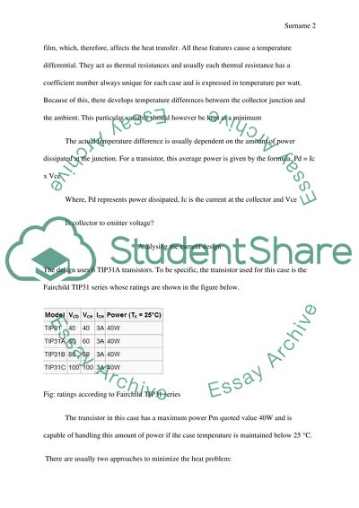
Case Study: Heat Transfer – Design Project In this study, we will come up with a design aimed at reducing the overheating of the garnt crane electronic system. The design will apply the heat sink technology. The system experience a temperature of 150 degrees at peak operation condition and thus this design will be able to lower this value to below 40. Introduction Heat transfer is the basic phenomenon for explaining the causes of heating of any electronic device. Most heavy load electronic devices face a challenge of overheating, which may lead to failure. This will be costly since there will be afrequent need for repairs. In the current setup of the electronics package, the heat generated by the transistors can only be lost through air convection. The temperature of the devicessurrounding, therefore, needs to be less than the allowable temperature of the device. At 150 degrees Celsius, the device is prone to damage. The introduced heat sink will however try to reduce the junction temperature for the device and ‘dump’ it in the surrounding media. Electronic device uses air as a medium.In a transistor; there exist connections between the casing and the junction and from the case to theheat sink. In addition, the contacts between the device and the sink usually contain a thin film, which, therefore, affects the heat transfer. All these features cause a temperature differential. They act as thermal resistances and usually each thermal resistance has a coefficient number always unique for each case and is expressed in temperature per watt. Because of this, there develops temperature differences between the collector junction and the ambient. This particular variable should however be kept at a minimum The actual temperature difference is usually dependent on the amount of power dissipated at the junction. For a transistor, this average power is given by the formula. Pd = Ic x Vce Where, Pd represents power dissipated, Ic is the current at the collector and Vce Is collector to emitter voltage? Analysing the current design The design uses 6 TIP31A transistors. To be specific, the transistor used for this case is the Fairchild TIP31 series whose ratings are shown in the figure below. Fig: ratings according to Fairchild TIP31 series The transistor in this case has a maximum power Pm quoted value 40W and is capable of handling this amount of power if the case temperature is maintained below 25 °C. There are usually two approaches to minimize the heat problem: 1. By operating the transistor in a most efficient possible way and this by selecting a class of biasing that offers high efficiency, as well as low power wastage. 2. Ensuring that the produced heat from the transistor is removed and transferred to the surrounding. The transistors are stacked together a feature that increases heat development. These transistors will however be the focus of this study since its where most of the heat is generated. Designmodifications Some modifications will have to be made on the current device. These modifications are as explained below: 1) Rearranging the transistors- In the current layout, the transistors are stacked together. This contributes to theaccumulationon heat thus increase in temperature. This proposed design will consider arranging the transistor and having some gap between them. The spacing ensures free circulation of air and heat loss from the transistor surfaces. 2) Fitting a heat sink, which will be attachedon, the transistors dissipation points? The heat sink will be designed to have a large surface area, and this will be achieved by making fins on it. 3) Introducing a fan for cooling the heat sink. A 12-volt fan will work for the design. Design of the heat sink The material commonly used for heat sinks is aluminium with some fins fitted for more effective heat dissipation. The fins increase the surface area over which heat dissipation takes place.Since thecostis a major factor; the ultimate choice for this design will be aluminium. Key considerations The sink chosen have should have a flat surface to enhance good physical contact. This will ensure maximum heat transfer. Grooves that match the transistors contact will be createdon the heat sink block. The heat sink will be fixed together with a heat-sink compound, which in this case we choose a thin rubber. However, unlike other devices where this compound is fitted with the transistor, in this case the rubber will be at the housing walls. This ensures direct contact between the two metallic parts for increased heat transfer. Choosing the appropriate heat sink We shall need to know the required power that need to be dissipated by the system. We consider the Power de-rating Graph for the TIP31 as shown below: Fig: power de-rating graph We shall take the maximum junction temperature as 150 °C. For the T!P31 transistor, the power dissipation is usually 5Watts. The average temperature of operation is approximately  From the graph, junction-case resistance is given as The maximum case temperature during dissipation °C The required heat sink temperature for this case is 40 °C Usually the maximum heat –sink temperature =max case temperature when dissipating-(power X thermal resistance) The provided thermal resistance Rth c-hsin between the casing and heatsink =2°C The maximum heat sink temperature will be: Tmax==124.4deg celcious. In order to reach the given temperature of 40°C, The heat sink thermal resistance will have to be more than,  In order to prevent any possibility of the temperature exceeding the value, we recommended a thermal resistance 15 °C/W We shall have to choose a heat sink and should be able to dissipate heat from transistor to the surrounding as quickly as possible in order to avoid overheating of the transistors. Heat-Sink Selection We need to select a heat sink meeting the required thermal resistance (15°C/Wfor this case). The volume of the heat sink need to be determined. The volumetric resistance for aluminium is approximately. The required volume of heat sink material for each transistor should therefore be,  This will be the amount of the material needed for design of heat sinks for each transistor. However, in order to designa heat sink, there are other parameters to consider most importantly, the fin density. The fin spacing is however a factor of fin density. We consider the table below showing various fin spacing against the length of fins. Fig: fin spacing versus flow and fin length. In this case, we are considering a case of 5m/s flow condition. Choosing a fin length of 300mm, the corresponding fin spacing will be 3.5mm. The number of fins required will be; say 43 fins. As earlier calculated, the required heat sink volume will be 6 x 10^6 mm3. For all six transistors, required heat sink  Determining required heat sink dimensions For maximum heat transfer from the transistor, two heat sinks on each side isideal. The fins will be arranged lengthwise as shown in the diagram below. Therefore, length of the heat sink will be 300mm and the width chosen is 150mm. Now to calculate thickness (t) of each heatsink we use the relation below; Therefore,  Therefore, the heat sink will be a rectangular aluminium block of length, width and height of 300mm, 150 and 2.7 respectively. The fins will be on some of the surface sections. The final design The block will have to be fitted on the circuit box with the transistors arranged lengthwise. The fan will also be fitted to face the direction of the fins. The diagrams below illustrate the Overall setup. Fig: Sketch of the aluminiumblock that will act as the heat sink Fig: sketch showing new arrangement of the transistors and the fins Fig: a sketch showing the overall setup of the design Conclusion Electronic devices usually face the challenge of overheating which is a major drawback since this might cause failure thus requiring frequent repairs. This design utilized the thermodynamic concept of heat transfers. The heat dissipation from the system required presence of a heat sink as well as a cooling mechanism. The material used for the heat sink is aluminium that was chosen for its low cost as well as excellent performance. The fan used will use a 12V motor and is to maintain airflow in the system. This design was however successful sinceits capable of maintaining the device’s temperature below 40 °C, which is a safe temperature. This design is however less costly ( Read More
Cite this document
  • APA
  • MLA
  • CHICAGO
(“Heat Transfer Design Project HOT Gantry Crane Research Paper”, n.d.)
Heat Transfer Design Project HOT Gantry Crane Research Paper. Retrieved from https://studentshare.org/design-technology/1670367-heat-transfer-design-project-hot-gantry-crane
(Heat Transfer Design Project HOT Gantry Crane Research Paper)
Heat Transfer Design Project HOT Gantry Crane Research Paper. https://studentshare.org/design-technology/1670367-heat-transfer-design-project-hot-gantry-crane.
“Heat Transfer Design Project HOT Gantry Crane Research Paper”, n.d. https://studentshare.org/design-technology/1670367-heat-transfer-design-project-hot-gantry-crane.
  • Cited: 0 times

CHECK THESE SAMPLES OF Reducing the Overheating of the Grant Crane Electronic System

Industrial Crane Accidents

To date, many reports relay crane-related accidents that could have been avoided if safety regulations were carefully considered.... Industrial crane operators are required to apply strict safety procedures to carry out their job properly.... Industrial crane accidents can happen anytime if workers practice negligence.... The complex and heavy structure of the crane implies the high demand for safety during operation in the workplace....
7 Pages (1750 words) Essay

Different Types of Electronic Displays

The paper "Different Types of electronic Displays" describes that there is little information concerning LCD substances.... OLED and plasma monitor function in a different manner and they do not need backlight, however, there is limited information (if they are hazardous or not) concerning them....
7 Pages (1750 words) Essay

Dockside Cranes

The responsibilities of those drivers became more important considering the safety concerns of the other workers and laborers involved in crane and cargo operations in the port.... One dockside crane had a ten-ton capability.... There are no available data on the cost of each equipment, meaning the amount of money then needed to complete a dockside crane set....
5 Pages (1250 words) Research Paper

Electronics as a Branch of Electrical Engineering

An electronic system will have input signals from transducers and output signals which are reconverted by other transducers to produce energy in various required forms.... hellip; It is possible that a new non-electronic technology might be discovered and makes the electronic stereo hafiz-system as dead and archaic as is the Edwardian today. ... In another example, both input and output of a communications system may be sound such as words or music....
11 Pages (2750 words) Essay

Dockside Gantry Crane

The paper "Dockside Gantry crane" gives information that design a Dockside Gantry crane in a Harbour as a part of the Material Handling.... hellip; Such a crane is capable of loading and unloading containers from very wide ships.... This crane is known to be made with the latest design of ZPMC.... The productivity can be increased up to 50% with the help of the new crane only if the process of loading and unloading can be enhanced....
7 Pages (1750 words) Essay

Grant Seeking In An Electronic Age

The paper 'Grant Seeking In An electronic Age' is focused on the map data which will assist the property owners where to install the dome cameras, privately controlled camera and the narrower surveillance cameras.... The map data will also help the property owners of Philadelphia....
1 Pages (250 words) Essay

Electronic Recruiting System Description

The author examines EmployDIVERSITY, Inc.... JobMonkey, Inc.... and the Workopolis.... om which cater the needs of not only the job seekers but also the employers through their job posting sites which provide access and link between those who are looking for jobs and the ones who are offering it… Bolded jobs and jobs extension price list also vary per package....
2 Pages (500 words) Assignment

Luffing Tower Crane Analysis

Safe system of Works ... The paper "Luffing Tower crane Analysis" analyzes risks, measures, statutory and other issues that play an important role in ensuring that luffing tower crane can successfully accomplishing duties of lifting loads.... nbsp;The luffing tower crane plays an important role in the construction of the car park since it is a four-story building.... It is very important to make a documentation of accomplishments and any problem associated with the crane....
7 Pages (1750 words) Term Paper
sponsored ads
We use cookies to create the best experience for you. Keep on browsing if you are OK with that, or find out how to manage cookies.
Contact Us