StudentShare
Contact Us
Sign In / Sign Up for FREE
Search
Go to advanced search...
Free

The Principles of the Super-heterodyne Receiver, Automatic Control in AM and FM Receivers - Assignment Example

Cite this document
Summary
The paper "The Principles of the Super-heterodyne Receiver, Automatic Control in AM and FM Receivers" discusses that one of the importance’s of the intermediate frequency production is that it provides all of the selectivity for the radio besides amplifying the signal produced in the RF section. …
Download full paper File format: .doc, available for editing
GRAB THE BEST PAPER93.1% of users find it useful
The Principles of the Super-heterodyne Receiver, Automatic Control in AM and FM Receivers
Read Text Preview

Extract of sample "The Principles of the Super-heterodyne Receiver, Automatic Control in AM and FM Receivers"

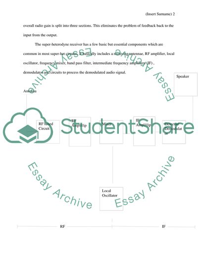
Communication Technology Part A: Question 1 Analogue Communication Question 1 The principles of the super-heterodyne receiver A super-heterodyne receiver, also known as super-het, uses frequency mixing in the conversion of received signal into a fixed intermediate frequency (IF) which can be conveniently processed than the original radio carrier frequency received at the antennae. It uses the same principle that all the modern television and radio use. Design and operation The super-heterodyne receiver bases its operation on heterodyning principles also known as frequency mixing. It mixes two input signal frequency to produce a new signal whose frequencies are the sum and difference of the original input frequency signals. The new frequencies are referred to as heterodynes. (Stark, 36)The super-heterodyne receiver works in three wide sections namely the RF section which extends from the antennae to the mixer, IF (intermediate frequency) section from the mixer to the detector and AF section from the detector to the speaker as shown in the block diagram below. The IF section is the most significant feature of the super-heterodyne receiver since the signal in the IF portion remains at a constant frequency regardless of the station tuned. Each of the three sections has a smaller gain since the overall radio gain is split into three sections. This eliminates the problem of feedback back to the input from the output. The super-heterodyne receiver has a few basic but essential components which are common in most super-het circuits. It basically includes a receiving antennae, RF amplifier, local oscillator, frequency mixer, band pass filter, intermediate frequency amplifiers (IF) , demodulator and circuits to process the demodulated audio signal. Antenna RF IF Basically the super-heterodyne receiver operates by mixing the input signal from the antennae with the signal generated by a local oscillator to produce sum and difference frequency components. The signal from the antennae is filtered in order to eliminate image frequency (the unwanted input frequency which is equal to the station frequency but with a doubled intermediated frequency) after which it is amplified by the RF amplifier. The image frequency produces an interference which is eliminated by the RF amplifier through sufficient attenuation on the input signal. (Stark, 38) The filtered and amplified signal is then passed through a mixer where it is mixed with frequency signal generated by a local oscillator fed into the mixer through another port. The locally generated signal by the local oscillator is a sine wave which mixes with the input signal shifting it to a specific intermediate frequency (IF). The intermediate frequency should be of a lower frequency to enable it pass through the higher performance fixed frequency filters at the AF section. This results into the generation of new frequencies at the sum and difference frequencies. The output signal at this stage is then passed through the IF section where it is filtered and amplified by the IF amplifier. The IF amplifiers accepts converted signals that falls within its pass-band while rejecting those that fall outside the pass-band. (Stark, 38) The IF signals is then passed through a demodulator which creates a copy of the original modulation through demodulation resulting into recovered audio signal. The demodulated signal is then passed through the audio section (AF section) where necessary amplification is done by the AF amplifier and finally presented to the speaker. According to Stark, one of the importance’s of the intermediate frequency production is that it provides all of the selectivity for the radio besides amplifying the signal produced in the RF section. It is also the basic feature of the super-het receiver since the signal at the IF stage stays at a constant frequency irrespective of the station tune (39) Part A: Question 2 Analogue Communication Automatic Gain Control in AM Receivers Automatic Gain Control (AGC), also known as Automatic Volume Control, is an adaptive system which adjusts the gain appropriately by feeding back the average output signal level for a range of input signal levels. It effectively raises the volume if the signal is weak and reduces it when the signal is strong. In most AM reception, RF and IF gain is automatically controlled in order to accommodate fading and avoid strong signal blasts in addition to avoiding missing the weaker signals while tuning a station across a band. The AGC is usually hidden from the external user despite the fact that it is universally present in most communication receivers. Automatic gain control is achieved in most communication receivers through the recovery of the DC signal from the detector stage that is proportional to the signal strength and applying it to the stages with gain control in a manner that it reduces the gain while increasing the strength. An increase in signal strength leads to a more negative AGC voltages in tube type receivers. In order to remove the audio components of the signal, the AGC signal must be low pass filtered otherwise the modulation of the incoming signal is suppressed by the AGC system. A variable attenuator between the input and the first active stage will ensure a simple method of gain control since gain control is usually distributed over a number of stages so that the gain in IF amplifiers is reduced first then the gain in RF is reduced only for sufficiently high level signals. The AGC signal is usually picked from the junction of the last IF transformer secondary and the detector diode load resistor. The signal is then passed through a series of high value resistors before it reaches the control grid return connection of each of the gain control stages. The AGC has a very high resistance so as not to overload the detector circuit besides adjusting the demodulator input level for optimum operation. Small amount of leakages will cause the AGC to malfunction since the gain of the controlled stages increases with increase in the AGC voltage. A Variable Gain Amplifier (VGA), whose gain is controlled by an external signal, is used to amplify the input signal. Further amplification is done to the output signal of the VGA by a second stage to generate an adequate level of voltage V0. The detector senses some of the output signal’s parameters (like the carrier frequency, amplitude and index of modulation) while filtering out the undesired components and finally comparing the remaining signal with the reference signal. The control voltage, V c , is generated from the result of the comparison and is used to adjust the gain. Automatic Frequency Control in FM Receivers Automatic Frequency Control (AFC) circuit is used in FM receivers whose oscillators tend to drift in frequency. According Rider, it is an arrangement for controlling the local oscillator frequency in such a way that a correct intermediate frequency (IF) is produced when a signal is received in a super heterodyne receiver (pg 26). The oscillator frequency tends to drift due to the changes in humidity or temperature which affects the values of the components, the frequency variations is then compensated by the AFC. Oscillators with phase-locked-loop do not need the AFC circuit since they do not have a drift in frequency. The received signal at the detector is checked by the AFC circuit to ensure that the radio is tuned to the station correctly; otherwise it sends a correction signal back to the oscillator forcing it to either increase or lower its frequency in order for a correct tune of the station. (Rider, 26) The Automatic Frequency Control presents a feedback system where the output signal of the demodulator is fed back to the local oscillator in order to keep the oscillator locked to a valid RF signal thus stabilizing the drift in frequency at the oscillator which results into a fine tune of a selected station. The AFC system is composed of two devices that is, a frequency discriminator and a variable reactance. The frequency discriminator must be able to change a frequency variation into a suitable direct voltage change which can be used for control purposes. The variable reactance on the other hand must have a value which can be controlled by the voltage changes produced by the frequency discriminator. (Rider, 28) The voltage output from the discriminator should be zero or the same value as that provided in the absence of a signal when the receiver is tuned exactly to the signal frequency to enable the controlled reactance have its normal value. The controlling voltage changes appropriately above or below the average voltage depending on the input signal frequency whether it is above or below the correct frequency. Part A: Question 3 Super-het Demodulator stage In super-het AM receivers, demodulation is carried out at the detector stage where the already amplified intermediate frequency (IF) undergoes demodulation process in order to extract amplitude modulation performed in earlier stages of the receiver from the signal. The demodulation of the IF signals in super-het AM receivers at the detector stage are carried out in two stages, the creation of baseband signal and the filtering stage. Baseband signal creation is the main element of the demodulation stage of the receiver, which is achieved through different ways one of which is the use of a simple diode to rectify the signal leaving the elements of the original signal. The rectified IF signal is then filtered to remove unwanted high frequency elements from the demodulation process. The audio signal can then be subjected to further stages of amplification. Part B: Question 1 VSAT Introduction Most organizations and businesses are increasingly moving their network communication infrastructure from closed-architecture and propriety protocols to internet protocol that is more user-friendly and offers internet for communicating business critical information in addition to familiar interface browser based applications. Internet protocol uses satellite based communication system, for this reason, VSAT network technology is rapidly growing since in addition to the above stated reasons it also offer its users, a cost effective solutions especially those seeking independent communication networks connecting a large number of geographically dispersed areas. (Grard, 4) Very Small Aperture Terminal (VSAT) refers to receive/transmit terminal installed at dispersed sites connecting to a central hub via a satellite through the use of small antenna dishes. The terminals are software driven with reliable data and voice transmission through a satellite with a speed of up to 2Mbps.It offers a value added satellite based services that are capable of supporting the internet, LAN, private dependable private and public networks and fax/voice communication. This technology is mostly used in areas where terrestrial communication is either unavailable or unreliable to provide aeronautical ground to ground communication. In certain terrains and conditions, VSAT are cost effective, flexible, scalable and easy to implement as compared to terrestrial communication. (Grard, 5) Network configuration The technology is a communication system based on wireless satellite technology that is made up small earth stations and typical antennae of diameter 1.8 meters usually less than 3 meters. The VSATs are connected by radio frequency (RF) links through a satellite with an uplink (from the VSATs to the satellite) and downlinks (from the satellite to the VSATs). The radio frequency is a modulated carrier conveying information which is received by the satellite from the transmitting earth stations, amplified then translated into a lower band signals which then transmitted to the earth stations within the view if its transmitting antenna. (Grard, 8)The VSAT network is composed of three main components: the master earth station, the VSAT remote earth station and finally the satellite. The master earth station is the central control center for the whole network and it is responsible with the management, configuration and monitoring of the network as a whole. The master earth station is has a fully redundant electronics with a large six meter antenna. It is closely monitored through the day every day since it’s the control center of the network and failures that may occur due to power shortage are eliminated the self contained backup power system. The VSAT remote earth station is the hardware installed at the subscribers’ residence which include ODU (the outdoor unit,), IFL (the interfacility link) and the IDU (the indoor unit). The ODU is composed of a standard 1.8 meter offset feed antenna, a low noise amplifier, a solid state amplifier (SSPA) and a feed horn. The indoor unit on the other hand is a small sized unit which houses communication electronics including interfaces with the subscribers’ equipments like the telephones and computers. A coaxial cable connecting the outdoor unit to the indoor unit makes up the IFL component of the VSAT remote earth station. (Grard, 13) The VSAT technology uses a geostationary satellite orbiting at thirty six thousand kilometer above the earth surface which beams all signals sent through each VSAT earth station. Frequency bands VSAT network are suppose to operate under the fixed satellite service (FSS) with an exception of data broadcasted in association with broadcasting of television or audio programmes which are broadcasted under broadcasting satellite services (BSS). For commercial applications VSAT network uses the C-band and the Ku-band, X-band is used by the military while only a few Ka-band made commercial. Benefits and Limitations According to the benefits and limitations of the VSAT network technology are always in comparison to the alternative communication system such as the terrestrial communication system. VSAT technology can be considered to be beneficial as compared to the terrestrial alternative in many different ways among them are reliability, accessibility, cost effectiveness, transmission quality high network performance, fast transmission, scalability, broadcast capability and its ability to handle large data volume.(21) On the other hand the terrestrial alternative has its advantages over the VSAT technology by exploiting its limitations such as extremely high initial cost, high risk profile, inadequate coverage in some areas like Africa, highly trained manpower for installation and maintenance. Conclusion VSAT provide better platform for communication than most of the other communication technologies in addition to the fact that it is extremely fast and highly reliable as compared to the other communication systems. Its benefits by far outweigh the limitations making it the best option in digital communication. Part B: Question 2 ITU The International Telecommunication Union (ITU) manages radio communication under the ITU Radio-communication sector which responsible for ensuring compatibility between radio systems used in different countries. Compatibility between radio systems is achieved by UTI in different ways including spectrum allocation, orbital positioning and registration and allocation of frequency. In addition, UTI manages satellite orbit resources and develop standards for radio-communication systems. This ensures effective use of the spectrum hence eliminating the incompatibility threat that may occur in the absence of spectrum management and also helps in preventing harmful interference of radio signal from different countries. Through spectrum management, ITU regulates the use of frequencies in order to promote effective use and net benefit. Radio spectrum resource management involves statically partitioning of the spectrum resource into blocks allocated for specific purposes such as cellular television and radio broadcast. Radio frequency interference between radio systems utilizing same operational frequency is regulated by UTI through frequency coordination. Frequency coordination involves all the steps an operator intending to start a new radio communication network must undergo before such network is up and running. This ensures proper frequency allocation hence eliminating incompatibility and interference that may occur due to poor frequency allocation. Frequency allocation is part of the electromagnetic spectrum management which regulates the use of radio frequency bands. Frequency usage by broadcasting firms is also regulated by UTI through the broadcast license which is a specific type of spectrum license which grants a license broadcasting firm to access or use a specific portion of the radio frequency spectrum. Through this radio frequency interference is prevented in that it ensures that different broadcasting firm does not share a radio frequency spectrum since each firm has a unique broadcast license that allocates it to a specific portion of the spectrum. Works Cited Penfold, R. A. Short wave superhet receiver construction. New York: Wiley; 2nd edition, 1991. Print. Superheterodyne Radio Receiver Basics:: Electronics and Radio Today Electronics and Radio Today for basic electronics and radio information, simple electronics projects and introductory articles.. Retrieved April 14, 2012, from http://www.electronics- s/radio/receivers/superheterodyne-radio/superhet-basics.php Top of Form Top of Form Stark, P. A, Rider.Elementary Communication. New York: Wiley; 2nd edition, 2006. Print. Top of Form Bottom of Form Bottom of Form Bottom of Form Maral, Grard. VSAT Networks (Second Edition). 2nd ed. Chichester: John Wiley Sons Ltd, 2004. Print. Read More
Cite this document
  • APA
  • MLA
  • CHICAGO
(The Principles of the Super-heterodyne Receiver, Automatic Control in Assignment - 1, n.d.)
The Principles of the Super-heterodyne Receiver, Automatic Control in Assignment - 1. Retrieved from https://studentshare.org/technology/1771829-electronic-communication-technology
(The Principles of the Super-Heterodyne Receiver, Automatic Control in Assignment - 1)
The Principles of the Super-Heterodyne Receiver, Automatic Control in Assignment - 1. https://studentshare.org/technology/1771829-electronic-communication-technology.
“The Principles of the Super-Heterodyne Receiver, Automatic Control in Assignment - 1”, n.d. https://studentshare.org/technology/1771829-electronic-communication-technology.
  • Cited: 0 times

CHECK THESE SAMPLES OF The Principles of the Super-heterodyne Receiver, Automatic Control in AM and FM Receivers

Relationship Between Senders and Receivers of Communication

Name Tutor Institution Subject code The relationship between senders and receivers of communication with the focus being on how messages are encoded and decoded Communication refers to the process by which information is passed from one person to another and feedback is received.... hellip; The process involves a sender and a receiver.... the receiver.... ? To deliver a message effectively, the sender and the receiver need to take care of: Maintenance of eye contact to increase message flow and interest in the information; it shows utmost attention and increases the likelihood that feedback will be received in the communication process....
8 Pages (2000 words) Essay

Super Heterodyne Receiver

Name of University College Program (Department) Course Code Super Heterodyne Receiver Semester and Year Name(s) of Author(s) Name of Instructor Abstract Super heterodyne receivers have in the recent years proved to be highly effective in overcoming several issues of the early signal frequencies and short wave amplifications and have proved to have essential applications in broadcasting media like the television and radio, as well as in security systems.... dvantages and Disadvantages of Super Heterodyne receivers: 13 7....
10 Pages (2500 words) Assignment

Super Heterodyne Receiver

All modern television and radio receivers virtually use the principle of super heterodyne.... These amplifiers were used in equipment for radio direction finding and Armstrong realized that if these receivers could be operated at a much higher frequency, they would be better and more effective.... Before Armstrong's invention, it had been noticed that if regenerative receivers were allowed to move into oscillation, it would be possible for other nearby receivers to start picking up stations on frequencies that were different from those that were actually being transmitted on by stations....
4 Pages (1000 words) Essay

Receiver Paper -- Ted Youth Speech

Ted Youth Speech: receiver paper University: Professor: Date: Ted Youth Speech: receiver paper Philip Koenig gave the speech on youth and civic engagement in Miami in Novembers 2003.... The speech focused on the needs for local community of youths to take an active role in the city's civic activities....
4 Pages (1000 words) Essay

Homodyne Receivers

he functionality of homodyne receiver is Homodyne receivers The homodyne architecture once overwhelmed by the more complex heterodyne architecture came back to utility as the performance and functionality requirements for many newer applications were demanding such a design.... ource: (Ma,2008)Advantages of Homodyne receiver The simplicity in its constitution and function is the prime advantage of this type of receivers.... A homodyne receiver is a particular architectural design of a… This design is comparatively simple in its constitution and function as it is the most natural solution to detect information transmitted by a carrier in just one conversion stage....
1 Pages (250 words) Essay

REPORT ON AM TRANSMISSION AND RECEPTION

Also there is very slight interference among TV, radio and cellphone… in am, the amplitude of the sinusoidal carrier wave is changed with the message signal while frequency and phase remain constant.... Before mixing the signal to local tune, the received signal efficiency is enhanced through a RF amplifier and then shifted to pre-define IF frequency, normally at 455 KHz in am broadcasting systems.... Though am is a simple technique to The following laboratory experiment is a practical demonstration of am technique with the application of a balanced modulator....
5 Pages (1250 words) Essay

Can Automatic Personal Categorization deal with User Inconsistency

It will… The paper will also discuss the SOM and LVQ, which both adhered to data mapping. automatic Personal Categorization can deal with user inconsistency in many ways.... Can automatic Personal Categorization deal with User Inconsistency?... The paper will discuss the advent of data based on normalization standards and derive an understanding to rectify anomalies from automation standpoint....
2 Pages (500 words) Book Report/Review

Critical Process Paper

At this stage, the transmission is done in one way only to ensure all the information fed into the AM is compatible with envelope detector receivers.... During this stage, both the phase and the mixed audio signals are modulated to avoid interfering with the envelope detector receivers.... his is a system used in the provision of information on fm broadcasts.... The C-QUAM signal is made up of two stages of conversion of sound signals including the quadrature PM version which is compatible and an am version that is conventional....
6 Pages (1500 words) Essay
sponsored ads
We use cookies to create the best experience for you. Keep on browsing if you are OK with that, or find out how to manage cookies.
Contact Us