StudentShare
Contact Us
Sign In / Sign Up for FREE
Search
Go to advanced search...
Free

Combinational Logics - Lab Report Example

Cite this document
Summary
The paper "Combinational Logics" tells us about several families of logic ICs. 74LS family: The 74LS (Low-power Schottky) family (like the original) uses TTL (Transistor-Transistor Logic) circuitry which is fast but requires more power than later families…
Download full paper File format: .doc, available for editing
GRAB THE BEST PAPER93.4% of users find it useful
Combinational Logics
Read Text Preview

Extract of sample "Combinational Logics"

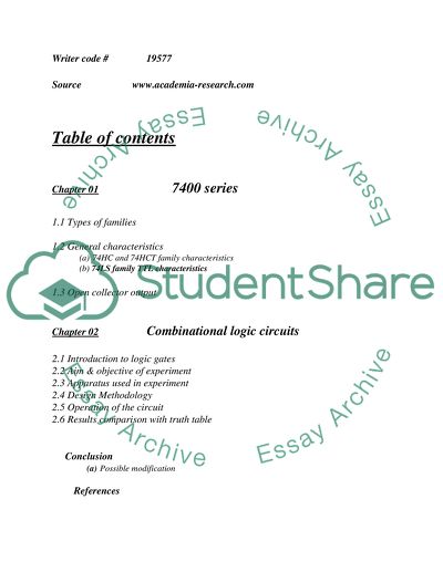
Introduction to combinational Logic circuits Comprehensive TechnicalReport Writer code # 19577 Source www.academia-research.com Table of contents Chapter 01 7400 series 1.1 Types of families 1.2 General characteristics (a) 74HC and 74HCT family characteristics (b) 74LS family TTL characteristics 1.3 Open collector output Chapter 02 Combinational logic circuits 2.1 Introduction to logic gates 2.2 Aim & objective of experiment 2.3 Apparatus used in experiment 2.4 Design Methodology 2.5 Operation of the circuit 2.6 Results comparison with truth table Conclusion (a) Possible modification References Chapter 01 Comment on the 7400 series There are several families of logic ICs numbered from 74xx00 onwards with letters (xx) in the middle of the number to indicate the type of circuitry, e.g. 74LS00 and 74HC00. The original family (now obsolete) had no letters, e.g. 7400 Family Types: 74LS family: The 74LS (Low-power Schottky) family (like the original) uses TTL (Transistor-Transistor Logic) circuitry which is fast but requires more power than later families. The 74 series is often still called the 'TTL series' even though the latest ICs do not use TTL! 74HC family: the 74HC family has High-speed CMOS circuitry, combining the speed of TTL with the very low power consumption of the 4000 series. They are CMOS ICs with the same pin arrangements as the older 74LS family. Note that 74HC inputs cannot be reliably driven by 74LS outputs because the voltage ranges used for logic 0 are not quite compatible, use 74HCT instead. 74HCT family: The 74HCT family is a special version of 74HC with 74LS TTL-compatible inputs so 74HCT can be safely mixed with 74LS in the same system. In fact 74HCT can be used as low-power direct replacements for the older 74LS ICs in most circuits. The minor disadvantage of 74HCT is a lower immunity to noise, but this is unlikely to be a problem in most situations. General Characteristics: 74HC and 74HCT family characteristics: 74HC Supply: 2 to 6V, small fluctuations are tolerated. 74HCT Supply: 5V 0.5V, a regulated supply is best. Inputs have very high impedance (resistance), Outputs can sink and source about 4mA if you wish to maintain the correct output voltage to drive logic inputs, but if there is no need to drive any inputs the maximum current is about 20mA. To switch larger currents you can connectatransistor. Fan-out: one output can drive many inputs (50+), except 74LS inputs because these require a higher current and only 10 can be driven. Gate propagation time: about 10ns for a signal to travel through a gate. Frequency: up to 25MHz. Power consumption (of the IC itself) is very low, a few W. It is much greater at high frequencies, a few mW at 1MHz for example. 74LS family TTL characteristics: Supply: 5V 0.25V, it must be very smooth, a regulated supply is best. In addition to the normal supply smoothing, a 0.1F capacitor should be connected across the supply near the IC to remove the 'spikes' generated as it switches state, one capacitor is needed for every 4 ICs. Inputs 'float' high to logic 1 if unconnected, but do not rely on this in a permanent (soldered) circuit because the inputs may pick up electrical noise. 1mA must be drawn out to hold inputs at logic 0. In a permanent circuit it is wise to connect any unused inputs to +Vs to ensure good immunity to noise. Outputs can sink up to 16mA (enough to light an LED), but they can source only about 2mA. To switch larger currents you can connectatransistor. Fan-out: one output can drive up to 10 74LS inputs, but many more 74HCT inputs. Gate propagation time: about 10ns for a signal to travel through a gate. Frequency: up to about 35MHz (under the right conditions). Power consumption (of the IC itself) is a few mW Open Collector Outputs: Some 74 series ICs have open collector outputs, this means they can sink current but they cannot source current. They behave like an NPN transistorswitch. The diagram shows how an open collector output can be connected to sink current from a supply which has a higher voltage than the logic IC supply. The maximum load supply is 15V for most open collector ICs. Open collector outputs can be safely connected together to switch on a load when any one of them is low; unlike normal outputs which must be combined usingdiodes. Chapter 02 Combinational logic circuits (Used in experiments) LOGIC GATES Logic gates take binary values and perform functions on them, similar to the functions found in simple algebra. Binary algebra is the set of mathematical laws that are valid for binary values. A binary value can only be a 1 or a 0. 1 is a high value, representing true and high voltage. 0 is a low value, representing a false value and low voltage. Logic gates are typically packaged in integrated circuits, although they can be constructed using analogue components. Integrated circuits allow multiple logic gates to be packaged in one chip and are usually quite reliable. Logic gates typically come in two flavours, TTL (transistor-transistor logic) and CMOS (Complementary Metal Oxide Semiconductor). One must be careful mixing the two types, there logic low and logic high are different voltages. A CMOS might take a TTL high as a LOW and a TTL will accept a CMOS low as a high. Because of this they are generally incompatible, but there are a few CMOS that can accept TTL inputs and vice versa. Aim & Objective of experiment: Basically, logic gates are used together to form a combinational circuit. So, the aim of this experiment is to construct a simple alarm circuit with logic gates (using IC 74LS00 and 74LS32). The main objective of this experiment is to learn the way by which it can become possible to gain experience in the operation and use of logic gates for a combinational logic application.. Basic logic types: (used in experiment) The buffer and NOT gates are the simplest of the logic gates. The buffer would be used as a digital signal booster, if a logic signal was to travel for some distance voltage drop from wire resistance would lower a logic high voltage so low that when it reaches its destination its read as a logic low, putting this in between would solve that problem. The buffers algebra function is B = A NOT gates simply change the input from a 1 to a 0 or vice versa. It is also called an inverter and has many uses in logic circuits. For example, you have 2 lights, but you only want 1 on at any one time, you would put a NOT gate between one light so when there is a logic high input 1 light is on and the other connected to the NOT gate is off and when there is a logic low input the second comes on because of the NOT gate. The circle on the end of the triangle indicates that an inverting gate and you can recognize any inverting logic device by this circle. The AND gate most commonly come in IC packages of 2 and 3 input versions. The output only produces a logical 1 when all of the inputs are 1. The OR gate has a minimum of two inputs and produces an output of 1 if at least one of the inputs has a value of 1. The NAND gate has a minimum of two inputs and is the equivalent of an AND gate with a NOT gate on the output. It produces a 0 only if all of the inputs are 1. The NOR gate has a minimum of two inputs and is the same as an OR gate with a NOT gate on the output. The NOR gate produces a 1 only if all of the inputs are 0. Design Methodology: There are varieties of options available to construct a simple alarm by using logic combinations. And the below diagram is one of the simplest architecture to make a simple alarm. A OR gate B C NAND gate Inverter 1. The circuit uses three inputs A, B & C. 2. A is the switch at the front of house. 3. B is the switch at the back of house. 4. C is ON / OFF switch of the alarm. 5. X is the output of OR gate. ( X = A + B) 6. Y is the inverted output of NAND gate. [Y = (X * C)'] 7. Then Z is the simple inverter. Operation of the circuit: The OR gate shows that, when ever any one of the input at OR gate set as high, the output at the OR gate become high (X = 1). Then this output (X) combines with the third input C (that is ON / OFF switch) and then become the input for NAND gate. And for NAND gate, both input must be high, to produce low output. And this low output, will be inverted with the help of an inverter (Z) at the end and produce a sound on alarm or blink the LED. Results comparison with truth table: The operation of the circuit & below truth table results shows that, to produce sound or for blink the LED the below condition should be satisfy. ON / OFF switch set as high with the output of OR gate (X) must be high. When ever the above condition occurs on the shown alarm circuit, this results for blinking the LED or to produce sound in alarm. On/Off Switch (Switch 3 ) Back Door (Switch 2 ) Front Door (Switch 1) X Y Alarm ( LED ) 0 0 0 0 1 0 0 0 1 1 1 0 0 1 0 1 1 0 0 1 1 1 1 0 1 0 0 0 1 0 1 0 1 1 0 1 1 1 0 1 0 1 1 1 1 1 0 1 Conclusion: Possible Modification: The above same result can be obtained by using AND gate in place of NAND gate, and by removing inverter (Z) from the output end This modified circuit work same as the given alarm circuit. And show the accurately the exact truth table result. References: "Combinational Logic & Systems" by David Belton - April 98 "Digital Electronics" by McGraw hill series. www.play-hookey.com/logic_families www.deyes.sefton.sch.uk/technology/AS&Alevel/combinational_logic.htm Read More
Tags
Cite this document
  • APA
  • MLA
  • CHICAGO
(“Combinational Logics Lab Report Example | Topics and Well Written Essays - 1500 words”, n.d.)
Combinational Logics Lab Report Example | Topics and Well Written Essays - 1500 words. Retrieved from https://studentshare.org/technology/1515499-combinational-logics
(Combinational Logics Lab Report Example | Topics and Well Written Essays - 1500 Words)
Combinational Logics Lab Report Example | Topics and Well Written Essays - 1500 Words. https://studentshare.org/technology/1515499-combinational-logics.
“Combinational Logics Lab Report Example | Topics and Well Written Essays - 1500 Words”, n.d. https://studentshare.org/technology/1515499-combinational-logics.
  • Cited: 0 times

CHECK THESE SAMPLES OF Combinational Logics

The Reliability of Logics

Since microcontrollers are programmed through these ics, so everything and object that is used computationally and mathematically in any field whether research, medical, defense, communication, manufacturing industries etc are the outcome of the great science of logics.... The details and explanations of logics are not that alike throughout the history, perhaps the philosophers are constantly engaged in critical argumentations about logical principles and logical views....
10 Pages (2500 words) Term Paper

Introduction to the Combinational Logic Circuit

The report "Introduction to the combinational Logic Circuit " calculates modification which can be obtained by using AND gate in place of NAND gate, and by removing inverter (Z) from the output end.... This modified circuit works the same as the given alarm circuit and shows the exact truth table result....
6 Pages (1500 words) Lab Report

Fuzzy Logic-Based Machines

This paper "Fuzzy Logic" discusses Fuzzy logic and Fuzzy logic based machines that are the future of Artificial Intelligence.... This paradigm of AI offers the capability to get things done in a more powerful way.... This research will present a deep analysis of the fuzzy logic and its functioning areas....
8 Pages (2000 words) Case Study

The Importance of Aristotle's Logic: Ontology

The paper describes a parallelism with the doctrine of prediction with his ontology in the Metaphysics, and the importance of Aristotle's logic, unlike more formal modern systems of logic, is that it is an ontology.... hellip; There is not a hard separation between the rules governing what is said of the sensible world, and the sensible world itself....
8 Pages (2000 words) Research Paper

Basic Elements and Attributes that Relate to Logic Circuits

The next section discusses logic gates starting with the three most basic gates followed by combinational logic gates.... "Basic Elements and Attributes that Relate to Logic Circuits" paper offers an insightful introduction regarding logic circuits featuring a detailed description of logic circuits and then proceeds to outline various electrical and electronic issues that relate to their design and implementation....
18 Pages (4500 words) Coursework

The Basic Elements and Attributes that Relate to Logic Circuits

"The Basic Elements and Attributes that Relate to Logic Circuits" paper offers an insightful introduction regarding logic circuits featuring a detailed description of logic circuits and then proceeds to outline various electrical and electronic issues that relate to their design and implementation....
15 Pages (3750 words) Coursework

The Resistors and Logic Circuits

This paper ''The Resistors and Logic Circuits '' tells that primary experiment objective is to study the flow of current and voltage drops in different circuit connections and fundamental logic circuits' operation.... Resistors, representing loads in new electrical circuits, were connected in series and then in parallel....
7 Pages (1750 words) Lab Report

Digital Logic Design Principles

This research will begin with the statement that since antiquity logic has been used to abstract arguments in the ordinary language.... This research tells that George Boole introduced the first serious mathematical representation in the mid-1800s.... hellip; The present research has identified that by 1950s, the Boolean principle had already become a standard part of the electronic design....
20 Pages (5000 words) Research Paper
sponsored ads
We use cookies to create the best experience for you. Keep on browsing if you are OK with that, or find out how to manage cookies.
Contact Us