StudentShare
Contact Us
Sign In / Sign Up for FREE
Search
Go to advanced search...
Free

Single Slit Diffraction and Double Slit Interference - Lab Report Example

Cite this document
Summary
This paper 'Single Slit Diffraction and Double Slit Interference' tells us that diffraction arises from how waves propagate as described by the Huygens–Fresnel principle. The wave propagates by considering every point on a wavefront. These secondary waves recombined and subsequently propagate forming the new wavefront.                                       …
Download full paper File format: .doc, available for editing
GRAB THE BEST PAPER98.3% of users find it useful
Single Slit Diffraction and Double Slit Interference
Read Text Preview

Extract of sample "Single Slit Diffraction and Double Slit Interference"

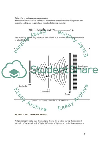
Experiment 3: Single slit diffraction & double slit interference. introduction Diffraction arises from the way in which waves propagate as described by the Huygens-Fresnel principle. The wave propagates by considering every point on a wavefront as a point source for a secondary wave. These secondary waves recombined and subsequently propagate forming the new wavefront. Interference occur when waves are added together, their sum is determined by the phase and the amplitude of the individual waves. The summed amplitude of the waves can have any value between zero and the sum of the individual amplitudes. Hence, diffraction patterns usually have a series of maxima and minima. Some of the simpler cases of diffraction are considered below. Single-slit diffraction The slit must satisfy two conditions in order the diffraction occur: first, the slit should has dimensions of infinitely length to width and second, the width of the slit is on the order of the wavelength of light being used. The wavefront from a light source will form secondary waves. The one located at the top edge of the slit interferes destructively with other secondary wave located at the middle of the slit, when the path difference between them is equal to '/2. Similarly, the secondary wave just below the top of the slit will interfere destructively with the secondary wave located just below the middle of the slit. Thus we can conclude that the condition for destructive interference for the entire slit is the same as the condition for destructive interference between double slits with distance equal to half the width of the slit. The path difference is given by: (3.1) Thus the minimum intensity occurs at an angle 'min given by (3.2) Where (d) is the width of the slit. Similarly the minima at angles 'n given by (3.3) Where (n) is an integer greater than zero. Fraunhofer diffraction can be used to find the maxima of the diffraction pattern. The intensity profile can be calculated from the following formula: (3.4) This equation applies only to the far field, which is at a distance much larger than the width of the slit. Figure (3.1): Young's Interference Experiment. double slit interference When monochromatic light illuminates a double slit aperture having dimensions of the order of the wavelength of light, diffraction of light occurs if the slits width much narrower than there lengths. The incident wavefront will divided into two point sources of light which can interfere with each other to produce an interference pattern The interference pattern is due to two types of interference: 1. Constructive Interference - When the path difference between the two beams in an integral multiplication of the wavelength. The result is brighter illumination in these regions when a crest of a wave meets a crest from another wave 2. Destructive Interference - When the path difference between the two beams in an odd multiplication of half a wavelength. The result is dark bands in these regions when a crest of a wave meets a trough from another wave Constructive interference occurs when: (3.5) Where: ' is the wavelength of the light, d is the separation of the slits, the distance between (b) and (c) in (Fig.3.1) n is the order of maximum observed (central maximum is n = 0), x is the fringe distance, the distance between the bands of light and the central maximum. L is the distance from the slits to the screen. This is only an approximation and depends on certain conditions. It is possible to work out the wavelength of the used light using this equation and the above apparatus. If (d) and (L) are known and (x) is observed, then ' can be easily calculated. Objectives: Examine the diffraction pattern formed by laser light passing through single and double slits. Verify that the positions of the minima in the diffraction pattern match the positions predicted by the theory To compare the actual He-Ne laser wavelength with one determined in the single slit experiment. To calculate the slit separation from the fringe separation in Young's double slit experiment. Equipment Required Part Description Part Qty Laser Assembly (He:Ne laser 632.8nm) 1 BSA: Beam Steering Assembly (flat mirrors) 2 TA: Target Assembly (holder) 1 TSS: Target, single slit 1 TDS: Target, dual slit 1 millimetre paper and Index card 1 Metric ruler and tape measure 1 Table (3.1): Required Equipment Beam Steering Assembly: (BSA) This assembly consists of the following parts: Table (3.2): parts required for Beam Steering assembly. Target holder Assembly (TA) This assembly consists of the following parts: Table (3.3): parts required for Target holder assembly. Cautions: Do not stare into the laser beam! It can mark a blind spot on your retina. See laser safety appendix. Beware of reflected laser light as well! To be able to see some of the diffraction patterns, this experiment will be performed in a darkened room. Extreme care should be taken concerning the He-Ne laser beam as your pupils will be expanded and will let in 60 times more light than in a lighted room. Be aware of your surroundings, Walking in a darkened room can be hazardous! Experimental Procedures 1. Mount a laser assembly at the rear of the table. Adjust the position of the laser such that the beam is parallel to both the edge and the surface of the table 2. Mount a flat mirror (beam steering assembly) approximately 450 on the far corner of the table (Fig. 3.4). Adjust the height of the mirror mount until the beam intersects the centre of the mirror and parallel to the left edge and the surface of the table. 3. Place a second beam steering assembly in line with the laser beam at the left corner of the optical table, (Fig. 3.4). Rotate and adjust the mirror mount until the laser beam is parallel to the front edge and the surface of the optical table. 4. Place an index card in a target holder and set it at the end of the table so that the beam hits the centre of the card. '500mm ' 2m 5. Laser beam alignment: use the index card with target holder for beam alignment such that the beam always hits the centre of the card in any position along the optical path this method is to align the beam vertically, for horizontal alignment, move the index card from the laser towards the first mirror such that the movement is parallel to the edge of the table. 6. Continue to move the index card along the optical path and adjust the mirror if the laser's spot is to the right/ left of the index card centre. single slit target 5. Place the single slit target ' 500 mm to the right of the last beam steering mirror and directly in line with the laser beam. 6. Adjust the target holder such that the laser beam strikes the target in the centre. 7. Use the index card as a screen and carefully adjust the last beam steering mirror to produce the brightest image. 8. Replace the index card with millimeter paper ' 2 m from the single slit (Fig.3.4). You should see a bright central band with several bright bands on each side. 9. Measure the distance (L) from the target to the screen (millimeter paper). 10. Mark and then measure the length of the dark fringes (distance between the centre of the first dark band and the central bright band (x1). 11. Repeat the measurement for the 2nd dark band, 3rd '..n dark band for both sides. double slit target 12. The Young's Double Slit Experiment can be performed with the same previous setup with replacing the single slit target with a double slit target and the millimeter paper used as the observation screen. Measure the slit to screen distance (L). 13. The interference pattern will now have a series of dark and bright bands. These fringes are the interference pattern of the double slit. Mark the locations of the minima x1, x2. . . of these closely spaced fringes. Calculate the average separations 'x = x1- x2 DATA SHEET single slit target Calculate: 1. Plot (n) against (xn)and find the slope 2. Giving that the wavelength of the He-Ne laser (' = 632.8 nm), calculate the slit width (d) n' = d sin (') ' n' = d ' d = ' L = ' L * slope (3.6) Where: d = the slit width ' = the wavelength xn = the dark band length L = the distance from the target to the screen n = dark band order number. double slit target 1. Calculate the fringe separation from '' = 'x/L (3.7) 2. the angles at which the bright fringes occur are given by 'r = d sin' = n ' (n = 1, 2, 3 . . .). Where d = the distance separating the two slits. n = dark band order number ' = the wavelength 'r = the difference in distances that waves traveled from the two slits to a point on the screen For small angles the sine can be replaced by its angle in radians, 'n ' sin'n thus 'n ' n'/d (3.8) The angular separation by neighboring fringes is then the difference between 'n+1 and 'n: '' = ' /d. (3.9) Giving that the wavelength of the He-Ne laser (' = 632.8 nm), calculate (d) Questions: 1. What is Constructive Interference and what is the expected result when it's happened' 2. What is Destructive Interference and what is the expected result when it's happened' 3. Give examples of diffraction in everyday life 4. Explain how Young perform his experiment without having a monochromatic source of available at that time. Results single slit target Table (3.4): result obtained for (xn) the dark band length for each (n) dark band order number Figure (3.6): plot of the dark band length vs. dark band order number ' = 632.8 x 10⁻⁹ m (known) L = 1.87 m d = ' L * slop d = 632.8 x 10-9 x 1.87 x 46 = 54433 x 10-9 m = 0.058 mm Note: the actual slit width = 0.002 IN = 0.051mm Using Eq.(3.6) we can calculate and verify the wavelength of the He:Ne laser giving that the slit width is known Thus ' = d ''( L x slop ) ' = 0.051 x10⁻³ ' (1.87 x 46) ' = 0.0006 x10⁻³ m = 600 nm double slit target The average separations between the fringes : 'x = x1- x2 = 6mm L = 2m The fringe separation: '' = 'x/L = 6x10⁻³ /2 = 3 x10⁻³ The wavelength of the He-Ne laser (' = 632.8 nm) and '' = ' /d d = ' / '' = 632.8 x10⁻⁹ / 3x 10-3 = 0.21 mm Note: the actual slits width = 0.051mm (0.002 IN) with 0.2mm (0.008in) spacing. Using Eq. (3.9) we can calculate and verify the wavelength of the He:Ne laser giving that the slits spacing is known '' = ' /d ' = '' x d ' = 3 x10-3 x 0.2 x 10-3 = 0.6 x 10⁻⁶ m ' = 600 nm Read More
Tags
Cite this document
  • APA
  • MLA
  • CHICAGO
(“Single slit diffraction & double slit interference Lab Report”, n.d.)
Retrieved from https://studentshare.org/science/1501622-single-slit-diffraction-double-slit-interference
(Single Slit Diffraction & Double Slit Interference Lab Report)
https://studentshare.org/science/1501622-single-slit-diffraction-double-slit-interference.
“Single Slit Diffraction & Double Slit Interference Lab Report”, n.d. https://studentshare.org/science/1501622-single-slit-diffraction-double-slit-interference.
  • Cited: 0 times

CHECK THESE SAMPLES OF Single Slit Diffraction and Double Slit Interference

The second part X-ray Diffraction (XRD) Powder X-ray

The X-ray diffraction has a base on interference of single chromatic X-rays constrictively together with crystalline samples.... The relation between the sample and the X-rays generates constructive interference, together with a diffracted ray if the conditions are favorable according to Braggs law, (n?... Powder X-ray diffraction is among the primary methods, which are used by solid-state chemists and mineralogists to examine physic-chemical build-up of solids, which are unknown to them....
14 Pages (3500 words) Book Report/Review

The effects of ergonomics, health and safety on productivity in hotels

CHAPTER 1 Productivity: Productivity is highly significant for nations, industries and organisations because the output of organisations and industries as a whole helps to improve national economy and improve the standard of living in general.... Therefore, efforts are being made world-wide to increase productivity in various industries....
5 Pages (1250 words) Dissertation

Single-Slit Diffraction and Interference

Single-slit diffraction and Interference Introduction Light can be bent from its ordinary straight-line path by means of reflection, refraction, as well as diffraction.... Thesis Statement: This paper will describe single-slit diffraction and interference.... Single-slit diffraction and Interference A plane wave of light travels in a straight line; so when such a wave passes through a rectangular slit, one may expect it to fall on a distant screen in the form of a bright rectangle with sharp edges....
4 Pages (1000 words) Essay

Refraction/Diffraction at Coastal Structures

These waves exhibit various phenomena like reflection, refraction, diffraction and shoaling.... These waves exhibit various phenomena like reflection, refraction, diffraction and shoaling.... hellip; diffraction takes place when the waves encounter an obstacle or protrusion; say an island, in its path.... In the subsequent paragraphs, we will elaborate on refraction and diffraction of water waves. ... diffraction takes place when the waves encounter an obstacle or protrusion; say an island, in its path....
2 Pages (500 words) Essay

Coherent Diffraction Imaging

Nowadays coherent diffraction imaging (CDI) is a modern approach of reconstruction of an object's image on the basis of its diffraction pattern, which is recorded as a… The collected diffraction pattern is measured and used for obtaining the image via iterative computational algorithms rather than via lenses.... In addition, the recent developments in coherent diffraction imaging are reviewed, with an emphasis on the impact that this technique has on biophysics, biochemistry and nanoscience....
20 Pages (5000 words) Essay

Potent and specific genetic interference by double-stranded RNA in Caenorhabditis elegans

There has to be certain requirements for the interference.... The interference process has two… nt features: (1) the effects that will enable the process to continue for many generations and (2) enough RNA antisense and sense preparations to trigger interference (Fire et al.... or instance, the above observation is crucial in understanding the interference in that Potent and Specific Genetic interference by Double-Stranded RNA in Caenorhabditis Elegans One of the significant functions of RNA is to impede the functions of endogenous genes....
1 Pages (250 words) Essay

Sunni-Shia Split

This is because the split is between two organized Islam groups who differ in several elements of their ethno-religious elements1.... The Sunni Arabs were considered to reap better benefits during the Sadam regime as… This changed after Hussein's fall and the Shia Arabs dominating the government3....
1 Pages (250 words) Essay

Light Background and Interferometry

The inception of wave theory firmly and accurately stated that light has energy especially because of its characteristics of refraction, diffraction, and interference.... Monochromatic light is light made of a single wavelength such as laser hence the word mono refers to one.... No light has a definite single frequency....
26 Pages (6500 words) Coursework
sponsored ads
We use cookies to create the best experience for you. Keep on browsing if you are OK with that, or find out how to manage cookies.
Contact Us