StudentShare
Contact Us
Sign In / Sign Up for FREE
Search
Go to advanced search...
Free

A Circuit Comprising a Resistor and Capacitor - Assignment Example

Cite this document
Summary
This assessment “A Circuit Comprising a Resistor and Capacitor” requires to make reports detailing how the student would construct and test an electronic circuit.  The scholar needs to detail an above-mentioned circuit to produce a first-order low pass filter with a given cut-off frequency.
 …
Download full paper File format: .doc, available for editing
GRAB THE BEST PAPER92.7% of users find it useful
A Circuit Comprising a Resistor and Capacitor
Read Text Preview

Extract of sample "A Circuit Comprising a Resistor and Capacitor"

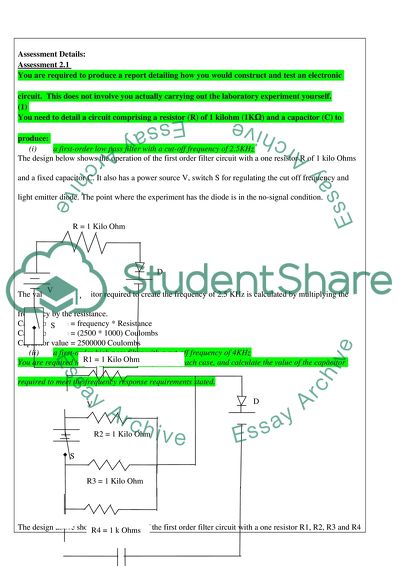
 Assessment Details: Assessment 2.1 You are required to produce a report detailing how you would construct and test an electronic circuit. This does not involve you actually carrying out the laboratory experiment yourself. (1) You need to detail a circuit comprising a resistor (R) of 1 kilohm (1KΩ) and a capacitor (C) to produce: (i) a first-order low pass filter with a cut-off frequency of 2.5KHz The design below shows the operation of the first order filter circuit with a one resistor R of 1 kilo Ohms and a fixed capacitor C. It also has a power source V, switch S for regulating the cut off frequency and light emitter diode. The point where the experiment has the diode is in the no-signal condition. The value of the capacitor required to create the frequency of 2.5 KHz is calculated by multiplying the frequency by the resistance. Capacitor value = frequency * Resistance Capacitor value = (2500 * 1000) Coulombs Capacitor value = 2500000 Coulombs (ii) a first-order high pass filter with a cut-off frequency of 4KHz You are required to produce a circuit diagram for each case, and calculate the value of the capacitor required to meet the frequency response requirements stated. The design above shows the operation of the first order filter circuit with a one resistor R1, R2, R3 and R4 each of 1 kilo Ohms. It also shows fixed capacitor C, a power source V, switch S for regulating the cut off frequency and light emitter diode. Capacitor value = frequency * Resistance Capacitor value = (4000 * 4000) Coulombs Capacitor value = 16000000 Coulombs (2) You need to detail a laboratory experiment stating how you would test these two circuits. You need to include the following sections in your account: (i) Aim of the experiment – a brief introduction to the experiment This is an experiment to test the behaviour of the designed first order filter circuits. It uses various ranges of cut-off frequencies to determine the appropriate capacitor values that are required for the first order filter circuits. (ii) Construction of the circuit: How you would construct the circuit suitable for this experiment: this may involve (a) a prototype board (soldered or plug-in type) using discrete resistor and capacitor components, or (b) a resistor box (i.e. the type with adjustable dials to select the required value) and a similar capacitor box. a) The process of circuit design for the experiment involves identifying the required components of the circuit, with the required specification. The next step involved is by drafting a prototype which has the presentations of the discrete resistor, capacitor box, power source, switch and the diodes. b) In an alternative design, after identifying the right components for the experiment, the experiment drafts a prototype presenting signal generator (In this case, the light emitter diode, capacitor box and capacitor box for the purpose of varying the resistance in the entire circuit). (iii) Equipment used for the experiment. This may involve a signal generator, an oscilloscope, suitable connecting wires and any other suitable laboratory equipment you would need. Component Symbol Variable Resistor Variable Capacitor Signal Generator (Light Emitter Diode) Wire Power Source Switch Oscilloscope (iv) Method/Process including Diagrams: How you would conduct the experiment. State any specific measures you need to take to ensure the experiment is carried out correctly and to obtain accurate results. Produce diagrams as necessary to show the set up of the experiment. To conduct the experiment, the experiment first designs the prototype of the design as a draft. The design will be as shown in the diagram below: In the diagram, O represents Oscilloscope, D represents the light emitter diode (Signal regulator), C represent capacitor (Capacitor Box), R represent the variable resistor (Resistor Box), S represent the switch while V represent the power source. To get accurate design, the design will have to use the resistor box to vary the values of the resistance and the Capacitor Box to vary the capacitor values for different observations of the oscilloscope frequencies as suggested by Dailey (2001). For example, the design will set the resistance at 4Kilo Ohms, and then the measurements of frequency from the oscilloscope are taken. (v) Measurements: state all measurements you need to take to derive the filters’ characteristics from 20Hz to 10 kHz. Produce a table that you would need to fill in for the experiment, e.g. frequencies measured, signal levels, etc. The measurements that will be needed to reduce the filter frequency from 20 KHz to 10 KHz is set by gradually reducing the resistance value until the required frequency value is obtained. This process assumes that the capacitor value is constant such as Q = 2000 Coulombs. Calculation then makes use of the model F = Q / R for various values of R. R (kΩ) Frequency (KHz) Signal Level 100 20 5 110 18.18181818 6.05 120 16.66666667 7.2 130 15.38461538 8.45 140 14.28571429 9.8 150 13.33333333 11.25 160 12.5 12.8 170 11.76470588 14.45 180 11.11111111 16.2 190 10.52631579 18.05 200 10 20 (vi) Calculations: Since the frequency response is given as decibels (dB) you need to convert the signal input / output levels in to dBs. (note – Gain, dB = 20log Vout / Vin ) The frequencies are then converted into dB by the following model dB = 20 log (Vout)/ (Vin). Take Vout /Vin for the third column. Signal Level (Vout/Vin) dB 5 13.97940009 6.05 15.63510749 7.2 17.14664993 8.45 18.53713418 9.8 19.82452151 11.25 21.02305045 12.8 22.14419939 14.45 23.19735694 16.2 24.19030029 18.05 25.12954412 20 26.02059991 Graphs Frequency against Resistance Signal Level against Resistance (vii) Conclusions and Discussion: State any issues which need special attention. Discuss any conditions, or factors that may influence the accuracy of results that may be obtained. In the experiment, there is need to ensure that the capacitor value remains constant so that there will be consistent results. It also requires every variable factor to be reset before taking any further measurements for the filter frequencies. Finally, there has to be a standard form of rounding off values. For example, all the values can be rounded off to 2 decimal places or to three significant figures. This creates an even treatment to all the measures, and generates proportional relationship between the variables. Reference Dailey, D., 2001. Electronic Devices and Circuits, Discrete and Integrated. New Jersey: Prentice Hall. Read More
Cite this document
  • APA
  • MLA
  • CHICAGO
(“A Circuit Comprising a Resistor and Capacitor Assignment”, n.d.)
A Circuit Comprising a Resistor and Capacitor Assignment. Retrieved from https://studentshare.org/physics/1802385-re-assessment-21-comprises-production-of-a-report-to-detail-how-you-would-build-and-test-a-filter-circuit
(A Circuit Comprising a Resistor and Capacitor Assignment)
A Circuit Comprising a Resistor and Capacitor Assignment. https://studentshare.org/physics/1802385-re-assessment-21-comprises-production-of-a-report-to-detail-how-you-would-build-and-test-a-filter-circuit.
“A Circuit Comprising a Resistor and Capacitor Assignment”, n.d. https://studentshare.org/physics/1802385-re-assessment-21-comprises-production-of-a-report-to-detail-how-you-would-build-and-test-a-filter-circuit.
  • Cited: 0 times

CHECK THESE SAMPLES OF A Circuit Comprising a Resistor and Capacitor

Charging and Discharging Capacitors

At t = 0, a resistor of 12 kilo-ohms is connected across the capacitor.... When a fully discharged capacitor is recharged the charge and voltage approach their maximum values exponentially according to' Kirchoff's Voltage Rule'.... hellip; When a capacitor is being charged, at t=0, the voltage across the capacitor terminals is 0.... As the charge builds up in the capacitor the voltage also increases.... A 20 microfarads capacitor is charged to 400 volts....
4 Pages (1000 words) Lab Report

Capacitance (Timing Circuits)

If a series combination of a resistor and capacitor are present such type of circuit is simplest timing circuit.... When discharging a capacitor through a resistor, V(t) = V0 * e-t/RC.... When charging a capacitor through a resistor, V(t) = Vf – Vf * e-t/RC (“Courseworkbank”).... n timing circuits when a capacitor is charged through a resistor then the voltage equation is given byV(t) = V0 * e-t/RC.... here V0 is initial voltage Similarly, when a capacitor is charged through a resistor then the voltage equation is given by V(t) = Vf – Vf * e-t/RC....
2 Pages (500 words) Essay

Engineering sceince

If the whole circuit is supplied from a 24V source, calculate: a: for initial current flowing in the circuit when the source is switched on as we know that capacitor acts as short circuit then the current flowing in the circuit is equal to the current flowing through 1.... kΩ resistor... In this circuit there are two nodes A & B along with two Loops L1 & L2....
5 Pages (1250 words) Essay

RC time constant of a capacitor

Parallel-plate capacitor is made from two parallel surfaces that conduct (Kaiser).... Then capacitance of such a… Considering the circuit as shown above, the capacitor has no charge.... At the beginning there is no voltage across capacitor but increases as charging continuous.... capacitor voltage Vc, increases towards Vb but asymptotically.... At this moment the capacitor was fully charged.... capacitor was recharged holding the voltage probe across capacitor....
4 Pages (1000 words) Essay

Function of filter circuit

In the research paper “Function of filter circuit” the author analyzes the capacitor and a resistor in the circuit.... b) Gain on the circuitGain across two components is derived asGc = |Hout(jw)|Gc = |(Vout(jw) / Vin(jw) )|Gc = 1 / √ (1 + (wRC) 2)GR = |HR (jw)| GR = |VR (jw) / Vin (jw)|GR = wRC / √ (1 + (wRC)2)Question 2The function of this diagramThis diagram represents the relationship between the capacitor and a resistor in the circuit, if they are arranged in series....
2 Pages (500 words) Coursework

Series and Parallel Connections

onclusionAround any closed loop in a circuit, the algebraic sum of potential differences must equal zero.... he voltage is divided based on the resistor values alone.... quation1: Equation 2: For circuit devices in series, the voltage drop across the entire series of devices is given by=For circuit devices in parallel arrangement, the voltage across each is the same, therefore the junction law applies.... Resistors in a series circuit divides the voltage Vs in the ratio Rx : R eq....
1 Pages (250 words) Lab Report

How Have Calculators Developed

The paper "How Have Calculators Developed" states that the chip of a calculator converts all the information fed to it in binary notations, which converts numbers and mathematical calculations into a two-digit system comprising of 0 and 1 (Richards, 1995).... hellip; Generally, calculators have made the process of making mathematical and scientific calculations utterly fast and quick....
5 Pages (1250 words) Essay

Resistor Manufacture and Optimization

the surface mount chip resistor and variable resistors).... hellip; a resistor controls electric current flow in an electric circuit, by resisting the current passing through it and allowing only a prescribed amount of it to pass to the other end of it.... The power of a resistor to resist is called resistance and is measured in Ohms symbolized as Ω.... The main characteristics of a resistor worth considering in detail are; noise, power, temperature coefficient, frequency response, voltage coefficient, reliability, physical size, mounting characteristic, and temperature rating....
9 Pages (2250 words) Term Paper
sponsored ads
We use cookies to create the best experience for you. Keep on browsing if you are OK with that, or find out how to manage cookies.
Contact Us