StudentShare
Contact Us
Sign In / Sign Up for FREE
Search
Go to advanced search...

Differential-Amp Circuits - Lab Report Example

Cite this document
Summary
This is due to the summing point constraints at the lower and upper LM1458C inputs; there is no current is drawn from the signal…
Download full paper File format: .doc, available for editing
GRAB THE BEST PAPER97.2% of users find it useful
Differential-Amp Circuits
Read Text Preview

Extract of sample "Differential-Amp Circuits"

Download file to see previous pages

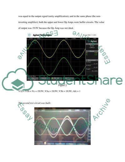
From figure 2, the input signal was equal to the output signal (unity amplification), and in the same phase (the non-inverting amplifier); both the upper and lower Op Amps were buffer circuits. The value of output was 19.9V because the Op Amp was not ideal. V1a = V1d = 0.2V; V1b= 0V; V3a = 1.16V; V3b = -0.96V; V3d = 2.12V; Afd = 10.6; Afd % Error = 4.4%; R4 = 0.97kΩ; R5 = 0.97kΩ; Average of R5 and R4= 0.97kΩ; R6 = 9.80kΩ; R7 = 9.84kΩ; Average of R7 and R6 = 9.82kΩ For better suppression or reduction of common mode gain, there was a potentiometer connected to the LM1458C op amps.

The potentiometer maintained output voltage at OV when differential input voltage is not applied. The nulling potentiometer improved common-mode gain of small input voltage by availing even smaller input voltages, V1a=0.2V was suppressed to V3a=1.16V as seen in figure 3. A bridge was made for the generation of two different voltages. There was a difference in between measured and calculated voltages due to tolerance or level of uncertainty. The differential gain was obtained through the connection of bridge to respective inputs of the amplifier.

The output voltages at the connected bridge were nearly similar to the unconnected bridge; this is because they are connected to the Op Amp inputs that have input resistance of not less than several hundred kΩ (LM1458C has 2MΩ); V1a was equal to V1b with voltage of 0.197V which corresponded to output 21.3V. The measured differential gain was 107.878. There was minimal signal picked as observed from the oscilloscope, this was due to drifting and DC offset. This problem was caused by low-frequency DC signal; since DC is zero frequency.

We could have constructed a high pass filter with very low cutoff frequency so that the Electro Cardiogram’s signal not to degrade. So both large capacitor of more than 1µF and large resistor of more than 1MΩ should have been put in place. The instrumentation

...Download file to see next pages Read More
Cite this document
  • APA
  • MLA
  • CHICAGO
(“Differential-Amp Circuits Lab Report Example | Topics and Well Written Essays - 750 words”, n.d.)
Differential-Amp Circuits Lab Report Example | Topics and Well Written Essays - 750 words. Retrieved from https://studentshare.org/miscellaneous/1669920-differential-amp-circuits
(Differential-Amp Circuits Lab Report Example | Topics and Well Written Essays - 750 Words)
Differential-Amp Circuits Lab Report Example | Topics and Well Written Essays - 750 Words. https://studentshare.org/miscellaneous/1669920-differential-amp-circuits.
“Differential-Amp Circuits Lab Report Example | Topics and Well Written Essays - 750 Words”, n.d. https://studentshare.org/miscellaneous/1669920-differential-amp-circuits.
  • Cited: 0 times

CHECK THESE SAMPLES OF Differential-Amp Circuits

Circuits with Feedback and Sine Wave Oscillators

Because of this, the signal is amplified and resend back to the input upon which it becomes amplified once more.... The process repeats… This process of sending part of the amplifier output signal back to the input of is often referred to as feedback (Ellinger, 2008).... As widely cited, as far as amplifiers are concerned, there are generally two These are positive or regenerative feedback and negative or degenerative feedback (Ellinger, 2008)....
10 Pages (2500 words) Coursework

Applying Positive Feedback Circuits With Feedback and Sine Wave Oscillators

It has been cited as being the best in creating the practical circuits due to its characteristic nature of being able to set rates, gains, alongside other significant parameters.... Moreover, the negative feedback can make the circuits self-correcting and stable.... This is based on the fact that it can be used in creating practical circuits given its characteristic of setting up rates, gains, alongside other significant parameters....
10 Pages (2500 words) Essay

The Fundamental Noise Source in Electronic Circuits

Every component in a circuit shows presence of random electrical noise in them which is mostly in terms of current or voltage.... This noise may be… When analyzing noise in an op- amp, one must consider the op-amp voltage and current noise and 1/f corner frequency, the band width and resistor noise....
5 Pages (1250 words) Assignment

The Fundamental Noise Source in Electronic Circuits

The amplifier has input noise voltage and input noise current spectral densities of Vn1and In1 The figure below is an inverting amplifier… The amplifier has input noise voltage and input noise current spectral densities of Vni and Ini respectively. Q3.... The figure below shows a differential amplifier employing The circuit is intended to amplify the signal V1 from a transducer with source resistance Rs....
5 Pages (1250 words) Assignment

Regulated Power Supply

It provides life to appliances, amplifiers, electronic circuits.... There are various types of rectifier circuits that offer half-wave and full-wave rectifications.... Some other types have complex circuits that use various capacitors, transistors, and regulators.... This is applicable in circuits that require accurate DC voltage and current....
8 Pages (2000 words) Assignment

Circuits with Feedback and Sine Wave Oscillators

This paper ''circuits with Feedback and Sine Wave Oscillators'' tells that Feedback is how information concerning the present or past tends to influence similar phenomena either in the future or present.... Given that the process entails a chain reaction of the cause and effect, forming a loop or a circuit, such an event....
11 Pages (2750 words) Coursework

Circuits with Feedback and Oscillators

This paper ''circuits with Feedback and Oscillators'' tells that The occurrence of an oscillator is such that part of the amplified signal is sent back to the input of that very amplifier (Ellinger, 2008)....  It has been cited as being the best in creating the practical circuits due to its characteristic nature of being able to set rates, gains, alongside other significant parameters....
12 Pages (3000 words) Report

Analog to Digital Inverters

"Analog to Digital Inverters" paper contains a summary theory of some electronic devices and systems, including the Analogue to Digital Converter (ADC) and R-2R ladder Digital to Analogue circuit.... The report also gives step by step procedure of simulating the designs using the OrCAD software.... nbsp;… Analog to Digital converters (ADC) are electronically integrated circuit that transforms a signal from analog (continuous) to digital (discrete) form....
14 Pages (3500 words) Coursework
sponsored ads
We use cookies to create the best experience for you. Keep on browsing if you are OK with that, or find out how to manage cookies.
Contact Us