StudentShare
Contact Us
Sign In / Sign Up for FREE
Search
Go to advanced search...
Free

Object and Data Modelling for Happy Tour - Assignment Example

Cite this document
Summary
This paper 'Object and Data Modelling' discusses web-based system for the flight company, that could allow to search for the availability and fares for the flight to the desired destination and other opportunities for their customers and describes this system on the field of diagrams: the use-case and use-case diagrams, detailed use-case models; activity, initial class and deployment diagrams etc.
 …
Download full paper File format: .doc, available for editing
GRAB THE BEST PAPER91.2% of users find it useful
Object and Data Modelling for Happy Tour
Read Text Preview

Extract of sample "Object and Data Modelling for Happy Tour"

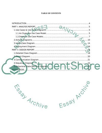
? Object and Data Modeling Assignment TABLE OF CONTENTS INTRODUCTION 3 PART I: ANALYSIS REPORT 4 Use-Cases & Use-Case Diagrams 4 1.An Overview Use Case Model 4 1.2.Detailed Use-Case Models 6 2.Activity Diagrams 9 3.Initial Class Diagram 13 4.Deployment Diagram 15 PART II: DESIGN REPORT 17 1.Detailed Class Diagram 17 2.Object Diagram 20 3.Communication Diagram 21 4.Sequence Diagram 22 5.Behavioral State-Machine Diagram 25 REFERENCES 28 TABLE OF FIGURES Figure 1: Use-case diagram for ticket booking & self-check-in system 5 Figure 2: Use-case diagram for searching the desired flight 6 Figure 3: Use-case diagram for booking the ticket 7 Figure 4: Use-case diagram for self-check-in 8 Figure 5: Activity diagram for booking tickets 10 Figure 6: Activity diagram for self-check-in 12 Figure 7: Initial class diagram 15 Figure 8: Deployment diagram 16 Figure 9: Detailed class diagram 19 Figure 10: Object model for searching the desired flights 20 Figure 11: Communication diagram for booking tickets 21 Figure 12: Communication diagram for self-check-in 22 Figure 13: Sequence diagram for searching available flights 23 Figure 14: Sequence diagram for self-check-in 24 Figure 15: Behavioral state-machine diagram for searching available flights 25 Figure 16: Behavioral state-machine diagram for self-check-in 27 INTRODUCTION A new economy flight company, Happy Tour, is looking for an online, web-based system that could allow their customers to (i) search for the availability and fares for the flight to the desired destination, (ii) make payments securely through a third-party payment system in order to book the tickets for the desired flight, (iii) view the real-time seating arrangement with available seats and select the desired seat in order to self-check-in, and (iv) print out the boarding card. PART I: ANALYSIS REPORT 1. Use-Cases & Use-Case Diagrams Use cases and use-case diagrams are the UML features for gathering and analysis of user-centric requirements. A use case can be defined as a particular purpose that can be achieved by the user (or say, actor) through the system (Chonoles & Schardt, 2003). A use-case diagram depicts a sequence of interactions between the actor and the system (Gomaa, 2011). 1.1. An Overview Use Case Model As shown in Figure 1, following are major use cases of the Ticket Booking and Self-Check-In System: Major Use Case 1: Search the desired flight After logging on to the Happy Tour’s website, the customer can search for the availability and fares for the flights to the desired destination. In order to carry out the search, the customers must provide mandatory information to the system which includes personal details, the departure airport, the destination airport, intended outbound flight date and time. The customer may also provide optional information – the date and time for return trip, to make the search more accurate. Assumption: The search result lists flights with available seats; in other words, if all the seats in the flight are booked then that flight won’t appear in the search result. Major Use Case 2: Book the ticket Once the customer has found the desired flight, she can move on to the booking process where she makes the payment through a third-party secure payment system. If the payment gets successfully processed, an automated confirmation email along with the receipt is sent out by the system to the email address provided by the customer. Major Use Case 3: Self-Check-In The customer can opt to perform self-check-in the booked flight anytime but 24 hours prior to the scheduled flight time. To self-check-in, the customer must search for the flight either through the booked flight number and booking reference number. If the flight is found and the customer’s booking is verified successfully, the system displays the real-time seating arrangement to the customer. The available seats are shown in blue color, while those already reserved are displayed in gray color. The customer can click on any one available seat to choose it, and then proceed to either cancel or confirm her choice. If the customer confirms her choice then the system prompts her to print out the boarding card. Once the boarding card is printed, the seat is confirmed and the customer cannot cancel or change it. Assumption: The customer must provide both the flight number and the booking reference number to search her booked flight. The seat will only be confirmed once the customer has printed out the boarding card successfully. If the boarding card was not printed out due any error, like, printer error, action cancelled by the user, then the seat will not be confirmed by the system. Figure 1: Use-case diagram for ticket booking & self-check-in system 1.2. Detailed Use-Case Models Detailed Use Case 1: Search the desired flight The user enters the mandatory details which includes personal details, the departure airport, and intended outbound flight date and time. The user may also enter the date and time for return trip if desirable. The user submits the information to the system. The system searches for the flights which match with the details provided by the user, and have available seats. The system displays the search result to the user. Figure 2: Use-case diagram for searching the desired flight Detailed Use Case 2: Book the ticket The user submits the booking request to the system for the desired flight. The system takes the user to the third-party payment system where the user goes through their payment procedure. Once the payment is successfully processed by the third-party system, the user is returned to the system. The system sends a confirmation email along with the receipt to the email address provided by the customer. Figure 3: Use-case diagram for booking the ticket Detailed Use Case 3: Self-Check-In The user enters the flight number and the booking reference number. The user submits the self-check-in request to the system. The system searches for the booked flight against the given flight number, and verifies the customer’s booking against the given booking reference number. If the flight is found and the customer’s booking is positively verified, the system displays the real-time seating arrangements. The customer clicks on any one of the available seats to choose it, and submits the request to the system to proceed. The system displays options to the customer to either cancel the selected seat, or confirm the choice. If the user confirms the choice, then the system prints out the boarding card for the user and confirms the seat. Figure 4: Use-case diagram for self-check-in 2. Activity Diagrams Figure 5 below depicts the activity diagram for booking ticket(s). The activity starts with the user submits the request for booking ticket(s) of the desired, available flight. Upon receiving the request, the system takes the user to the third-party system for the payment; it is assumed that the system also sends charges details so that the third-party system knows the exact amount to charge from the customer. As shown in the figure, the third-party system takes all necessary payment details from the user, and process the payment. In case if the third-party system fails to process the payment then the activity is terminated and the user is required to again log on to the Happy Tour website and follow the same activity from the beginning. On the other hand if the payment is processed successfully, then the third-party system sends the user back to the Happy Tour website along with the receipt details of the payment. Upon receiving the receipt details, the system creates a booking against the receipt and sends out a confirmation email, containing the flight and the receipt details, to the customer’s email address. Figure 5: Activity diagram for booking tickets Figure 6 shows the activity diagram for self-check-in which starts when the user submits the flight as well as the booking reference number to the system. The system first searches for the given flight number; if the flight is not found then the activity terminates – means user has to start the self-check-in process from the beginning. However, if the system finds the flight number, then it confirms the customer’s booking in the flight through the given booking reference number. In case if no booking is found for the customer in the flight, then the activity terminates; on contrary, if the booking is found in the flight for the customer, then the system displays the seating arrangement to the customer such that the available seats are shown in blue color while the reserved seats are displayed in gray color. The user can select the seat(s) for each ticket by clicking on the available seats; for example, if the customer has booked two tickets, then the system allows the user to select any two seats from the available ones. Once the customer has selected the desired seats, the user can proceed ahead to confirm the selected seat(s); however, the user may cancel the selected seat(s) if wishes in case of which the activity terminates immediately. If the customer confirms her selected seat(s), then the system prints out the boarding card for each ticket. Figure 6: Activity diagram for self-check-in 3. Initial Class Diagram Figure 7 depicts the initial class diagram for the Happy Tour system that contains 4 major entities of the system – Customer, Booking, Flight, and Seat. The diagram shows important attributes and operations for each entity, the associations that exist between them, and the multiplicity for each association. Entity Name Associated Entity Multiplicity Description Customer Flight 0..* The customer book seat(s) in the flight. The multiplicity 0...* means that when an instance of Flight exists, it can either have no instance or many instances of Customer associated with it. Booking 1 The customer creates booking. The multiplicity 1 means that when an instance of Booking exists, it must have one instance of Customer associated with it. Seat 0..1 The customer reserves seat(s). The multiplicity 0..1 means that when an instance of Seat exists, it can either have no instance or only one instance of Customer associated with it. Booking Customer 1..* The multiplicity 1..* means that when an instance of Customer exists, it can either have only one instance or many instances of Booking associated with it. Flight 1..* The booking is created for the flight. The multiplicity 1..* means that when an instance of Flight exists, it can either have only one instance or many instances of Booking associated with it. Flight Booking 1 The multiplicity 1 means that when an instance of Booking exists, it must have one instance of Flight associated with it. Customer 0..* The multiplicity 0..* means that when an instance of Customer exists, it can either have no instance or many instances of Flight associated with it. Seat 1 The flight has seats. The association between the two entities is Composite because Seat is part of the Flight, and therefore, when a Flight instance is destroyed, the Seat instances are automatically destroyed as well. The multiplicity 1 means that when an instance of Flight exists, it will always have at least one instance of Seat associated with it. Seat Customer 0..1 The multiplicity 0..1 means that when an instance of Customer exists, it can either have no instance or only one instance of Seat associated with it. Flight * The multiplicity * means that when an instance of Flight exists, it has many instances of Seat associated with it. Figure 7: Initial class diagram 4. Deployment Diagram Figure 8 shows the proposed deployment plan for the Happy Tour system. As shown in the figure, the users will access the system through their Internet browsers, such as, Internet Explorer, Firefox Mozilla, Google Chrome, because the system is web-based. The browsers will forward the user’s requests to the system’s Web Server through the Internet. A Web Server is a computer that is available on the Internet, and has software that enables it to host websites (Bishop et al., 2010). As shown in the diagram below, the web server is connected to an Application Server (a computer on a network that provides the business logic for an application program) which contains all the business logic of the web pages, and contains web service definition for the third-party payment system. The application server is connected to the Database Server through JDBC, and can access the third-Party payment system through Internet (here we have assumed that the third-party payment system is exposed as a web service on the Internet). Figure 8: Deployment diagram PART II: DESIGN REPORT 1. Detailed Class Diagram Figure 9 depicts the detailed class diagram for the Happy Tour system that contains all the entities of initial class diagram plus 2 additional entities – Airport and Ticket. As shown in the diagram, some associations in the initial class diagram are modified, and some new associations are defined due to the addition of two new entities. Entity Name Associated Entity Multiplicity Description Customer Flight 1..* The multiplicity 1..* means that when an instance of Flight exists, it can either have one instance or many instances of Customer associated with it. Booking 1 Same as in initial class diagram. Booking Customer 1..* Same as in initial class diagram. Flight 1..* Same as in initial class diagram. Ticket 1 The multiplicity 1 means that when an instance of Booking exists, it must have one instance of Ticket associated with it. Flight Booking 1 Same as in initial class diagram. Customer 1..* The multiplicity 1..* means that when an instance of Customer exists, it can either have one instance or many instances of Flight associated with it. Seat 1 Same as in initial class diagram. Airport 0..* The multiplicity 0..* means that when an instance of Airport exists, it can either have no instance or many instances of Flight associated with it. Seat Flight * The multiplicity * means that when an instance of Flight exists, it has many instances of Seat associated with it. Airport Flight 2 The multiplicity 2 means that when an instance of Flight exists, it must have 2 instances of Airport associated with it. Ticket Customer 1..* The multiplicity 1..* means that when an instance of Customer exists, it can either have one instance or many instances of Ticket associated with it. Booking 1..* The multiplicity 1..* means that when an instance of Booking exists, it can either have one instance or many instances of Ticket associated with it. Figure 9: Detailed class diagram 2. Object Diagram Figure 10 depicts the object diagram that illustrates the part of the detailed class diagram (see Figure 9), containing concrete objects of classes which are involved in the use case for searching the desired flight. Figure 10: Object model for searching the desired flights 3. Communication Diagram Figure 11 depicts the communication diagram for booking tickets. As shown in the figure, there are 3 classes involved – Customer, Booking, and Ticket. The process is initiated by the actor i.e. the user by performing some action (like for example, clicking the available flight) which calls BookTicket() method on the object, c1, of type Customer (Step 1). The method invokes the booking request in response to which the system takes the user to the third-party system where the user goes through the payment procedure to make the payment (Step 2). Once the payment is made by the customer, the system creates ticket(s) (Step 3), book those tickets to generate a booking a reference number (Step 4), and sends out the confirmation email containing the receipt and the flight details (Step 5). Figure 11: Communication diagram for booking tickets Figure 12 depicts the communication diagram for self-check-in process that includes 3 classes– Customer, Booking, and Flight. The process is initiated by the actor i.e. the user, by clicking a link on a Happy Tour website that calls SelfCheckIn() method on the object, c1, of type Customer (Step 1). The method invokes the self-check-in request in response to which the system takes the user to the self-check- in page. At self-check-in page, the user enters the flight number and the booking reference number; this information is used by the system to verify customer’s booking in the specified flight (Step 2). Once the booking is verified, the system displays the seating arrangements in the flight (Step 3). The user then selects the desired seat(s) by clicking on the available seats (Step 4). If user confirms her selection(s), then the system prints out the boarding card(s) for the selected seat(s). Figure 12: Communication diagram for self-check-in 4. Sequence Diagram Figure 13 depicts the sequence diagram for searching the available flights. The process is initiated by the customer (actor) by performing some action (like for example, clicking the ‘Search’ button) that calls SearchFlight() method on the object, c1, of type Customer. The method invokes the request in response to which the object, c1, requests for the list of all available flights from the object, Flights, of type List. As shown in the figure, the object, Flights, loops through the list of all the objects of type Flight that it contains, and calls the IsFlightAvailable() method on each object in order to determine the availability of the flight. Once the object, Flights, has finished looping through all the flight objects, it returns the filtered list to the object, c1, which then displays this list to the user on the website. Figure 13: Sequence diagram for searching available flights Figure 14 depicts the sequence diagram for self-check-in. The process is initiated by the customer (actor) by performing some action (like for example, clicking the ‘Self-Check-In’ button on self-check-in page) that calls SelfCheckIn() method on the object, c1, of type Customer. The object, c1, requests for the object, Booking, of type List to verify the booking of the customer in the specified flight. As shown in the figure, the object, Bookings, loops through the list of all the objects of type Booking that it contains, and matches the booking reference number and the flight number with that provided by the customer at the self-check-in page. Once the object, Booking, has finished looping through all the Booking objects, it returns the search result to the object, c1, of type Customer. If the search result is positive, then the object, c1, of type Customer calls the DisplaySeatArrangement() method on object, f1, of type Flight to display the real-time seat arrangements in the flight with available seats and reserved seats in blue and gray colors respectively. The customer selects seat(s) by clicking on the available seats, and proceeds to next step to confirm her selected seat(s). If the customer confirms her selection(s), then the object, c1, of type Customer first calls SelectSeats() method on object, f1, of type Flight to update the seats information in the flight, and then calls PrintBoardingCard() method on object, b1, of type Booking. Figure 14: Sequence diagram for self-check-in 5. Behavioral State-Machine Diagram Figure 15 depicts the behavioral state-machine diagram for searching available flights. As shown in the diagram, following are the states of the use case: State 0: Start State 1: The user logged on to the website. State 2: The user entered details to search the desired flight. State 3: The system searched the flights, based on the details provided by the user. If the search result returns no flight, then the system moves to State 4, otherwise, to State 5. State 4: The system displayed an empty the grid, and moved to State 6. State 5: The system displayed a grid populated with the list of available flights. State 6: End Figure 15: Behavioral state-machine diagram for searching available flights Figure 16 depicts the behavioral state-machine diagram for self-check-in. As shown in the diagram, following are the states of the use case: State 0: Start State 1: The user logged on to the website. State 2: The user clicked the link to navigate to self-check-in page. State 3: The user entered the flight number and the booking reference number. State 4: The system searched the flight number and the booking reference number to verify the booking. If the booking is verified positively, then the system moves to State ; otherwise it moves to State 5. State 5: The system displayed the real-time seating arrangements of the flight with available seats as well as reserved seats in blue and gray colors respectively. State 6: The user clicked the available seat(s) to select it. State 7: The user either confirmed or cancelled the selected seats. In case if the user confirmed the selection(s), the system moves to State 8; otherwise, it moves to State 9. State 8: The system printed out the boarding card(s) for the selected seat(s), and moved to State 10. State 9: The system cancelled the selected seat(s). State 10: End Figure 16: Behavioral state-machine diagram for self-check-in REFERENCES Bishop, S., Shuman, J. & Waxer, B.M., 2010. The web collection revealed: Adobe Dreamweaver CS5, Flash CS5, and Fireworks CS5. New York: Cengage Learning. Chonoles, M.J. & Schardt, J.A., 2003. UML 2 for dummies. NewYork: Wiley Publishing, Inc. Gomaa, H., 2011. Software modeling & design: UML, use cases, patterns, & software Architectures. New York: Cambridge University Press. Read More
Cite this document
  • APA
  • MLA
  • CHICAGO
(“Object data modelling Essay Example | Topics and Well Written Essays - 5000 words”, n.d.)
Object data modelling Essay Example | Topics and Well Written Essays - 5000 words. Retrieved from https://studentshare.org/information-technology/1402043-object-data-modelling
(Object Data Modelling Essay Example | Topics and Well Written Essays - 5000 Words)
Object Data Modelling Essay Example | Topics and Well Written Essays - 5000 Words. https://studentshare.org/information-technology/1402043-object-data-modelling.
“Object Data Modelling Essay Example | Topics and Well Written Essays - 5000 Words”, n.d. https://studentshare.org/information-technology/1402043-object-data-modelling.
  • Cited: 1 times

CHECK THESE SAMPLES OF Object and Data Modelling for Happy Tour

Object Oriented Programming

In addition, programmers can create relationships between one object and another.... In simpler terms, it is a type of programming in which programmers define not only the data type of a data structure, but also the types of operations (functions) that can be applied to the data structure.... In this way, the data structure becomes an object that includes both data and functions.... Each object is capable of receiving messages, processing data and sending messages to other objects....
4 Pages (1000 words) Essay

Building Information Modelling

The potentiality of Building Information modelling (BIM) in the construction companies operating in the West Midland region is undertaken in this research.... The potentiality of Building Information modelling (BIM) in the construction companies operating in the West Midland region is undertaken in this research.... The data collection exercises adopted included survey process using a detailed questionnaire and also personal interview based on a prepared set of questions....
55 Pages (13750 words) Dissertation

Data Acquisition and 3D Modelling

The paper "3D data Acquisition and Modeling" proves 3D data acquisition and modeling techniques have the potential of being used with the full propensity in the diversified and versatile areas such as the medical sciences or the Oil exploration industry, for the betterment of humankind.... hellip; data acquisition, with respect to 3D modeling, refers to the collection of data that is used to represent a physical object that exists....
7 Pages (1750 words) Speech or Presentation

Significance of Business Process Modelling in Modern Day Context

rom this study it is clear that business process modelling's chief objective is to enhance the performance of the business by optimising the effectiveness of connecting activities in the provision of the products or services.... The chief aim of the essay is to comprehend the significance and the benefits of business process modelling in modern day context.... It will begin with the discussion of the meaning of the business process modelling with certain examples....
14 Pages (3500 words) Essay

Object Oriented Databases

For instance, a ball is an object and its attributes are its color and its shapes.... Without a doubt, a database is an excellent way to store and access data.... An object oriented database stores data and information in the form of objects.... Actually, OODBMS stores objects instead of data, such as real numbers, strings and integers.... These databases are believed to be very useful for businesses when they have huge data and high performance is required....
6 Pages (1500 words) Research Paper

Object Role Modeling (ORM)

This paper will detail in full the topics that comprise the data management spectrum as well as training and end-user tools that are instrumental in ensuring that all employees within a company that is getting ready to implement data management disciplines.... nbsp;… A database management system is a suite of computer programs designed to manage large sets of structured data and is responsible for running operations from data requested by numerous clients....
40 Pages (10000 words) Term Paper

The Effectiveness of Video Modelling

The current paper “The Effectiveness of Video modelling” reviews and justifies the need to research the effects of video modeling on teaching and learning achievements for students with autism in Saudi Arabia.... The topic, research statement, and rationale for the research are provided....
12 Pages (3000 words) Research Paper

Commercial Software Packages and Computer Assisted Design

It has six types, parametric modelling, Constructive Solid Geometry (CSG), hybrid, Boundary representation (Brep), feature-based and dynamic solid modelling .... Such programs produce a realistic model in which the design object is up to the expectations of the designers, the production costs are lower and potential problems are solved early by the designers .... Following is the illustration of the 3D CAD:Figure 3: Example of 3D CAD 3D Wireframe and Surface ModelingThis generic type creates the inner-structure of an object that is skeleton-like....
8 Pages (2000 words) Assignment
sponsored ads
We use cookies to create the best experience for you. Keep on browsing if you are OK with that, or find out how to manage cookies.
Contact Us