StudentShare
Contact Us
Sign In / Sign Up for FREE
Search
Go to advanced search...
Free

The Single Phase Transformer - Lab Report Example

Cite this document
Summary
The author states that the transformer is not ideal and has non-ideal parameters. By Open and short circuit tests, these lossy behaviors are recorded. Its efficiency is observed with load current varying. From the efficiency plot, it can be inferred that loss is dependent on the load current…
Download full paper File format: .doc, available for editing
GRAB THE BEST PAPER96.9% of users find it useful
The Single Phase Transformer
Read Text Preview

Extract of sample "The Single Phase Transformer"

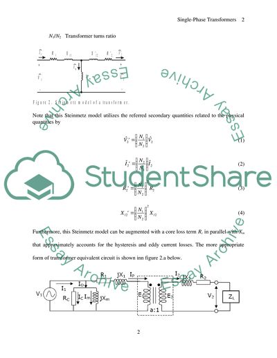
Introduction Transformer is a device that transfers electrical energy from one circuit to another which are kept electrically isolated. It does it through inductive or more specifically magnetic coupling. As shown in figure 1, change in voltage in primary winding creates changing magnetic flux that cuts the secondary winding and produces a proportionate secondary voltage. Its major application is to change the current or voltage level before transmitting electrical energy over long distance. Figure 1 shows the transformer schematic symbol and the corresponding commonly used Steinmetz model is shown in Figure 2. Therein, the model voltage and current phasors are defined as: Primary side voltage (V) Primary side current (A) Referred secondary side voltage (V) Referred secondary side current (A) Magnetizing current (A) The model parameters are: R1 Primary coil resistance () Xl1 Primary coil leakage reactance (H) Rc Core loss resistance () Xm Core magnetizing reactance () R2 Referred secondary coil resistance () Xl2 Referred secondary coil leakage reactance (H) N1/N2 Transformer turns ratio Note that this Steinmetz model utilizes the referred secondary quantities related to the physical quantities by (1) (2) (3) (4) Furthermore, this Steinmetz model can be augmented with a core loss term Rc in parallel with Xm that approximately accounts for the hysteresis and eddy current losses. The more appropriate form of transformer equivalent circuit is shown inn figure 2.a below. Figure 2.a Determining resistance The resistance parameters R1 and R2 can be found by applying DC voltage to the respective windings. For example, if a DC voltage is applied to the primary winding, the Steinmetz model predicts the equivalent circuit shown in Figure 3. The primary resistance can then be determined by (5) The same procedure can be used to find the secondary resistance R2. Note that the turns ratio is needed to refer this resistance to the primary. This is usually given by the transformer manufacturer. Reactances If the secondary of the transformer is short-circuited, the equivalent circuit can be approximated as shown in Figure 4. In this case, the magnetizing impedance is assumed to be much larger than the secondary resistance and leakage impedance. This is typically a good assumption for practical transformer designs. From the voltage, current, and power measurements, the magnitude and angle of the short-circuit impedance can be determined as (6) (7) (8) From the imaginary part of this impedance, the sum of the primary and secondary leakage reactance can be found. In particular, (9) The individual leakage reactance can be determined if it is assumed that (10) Although it is possible to perform other tests on the transformer to determine a more exact relationship between Xl1 and Xl2, (10) is a good approximation. An alternate method of determining the leakage reactances is to set (7) equal to the short-circuit impedance magnitude which can be written as (11) Using (11) along with the resistances, the sum of Xl1 and Xl2 can be determined. This method is convenient when watt-meters are not accessible. The next test involves open-circuiting the secondary winding and applying rated voltage to the primary winding. Under this condition, the Steinmetz equivalent circuit, including the core loss term, reduces to that shown in Figure 5. As can be seen, the open-circuit impedance is (12) (13) (14) Using the measured open-circuit impedance as well as R1 and Xl1, the core admittance can be determined by (15) Using this admittance, the magnetizing reactance and core loss resistance can be found from (16) (17) An alternate method for determining Xm is to set the magnitude of the measured open-circuit impedance equal to (18) This method does not require measurement of power. However, there is not enough information to calculate the core loss resistance. Equipment 1) Single phase transformer: The Lab’s variable AC source is a complex device, which is designed to provide safety conditions of an experiment. It consists of single phase transformer, variac and lamp bulb is series with the output. 2) AC wattmeter: Electric power is measured by means of a wattmeter. This instrument is of the dynamic type. It consists of a pair of fixed coils, known as current coils, and a movable coil known as the potential coil. A simplified electrodynamics wattmeter circuit is shown in figure below. Figure: AC Wattmeter The current coil of the wattmeter is connected in series with the circuit (load), and the potential coil (movable coil) is connected in parallel. When line current flows through the current coil of a wattmeter, a field is set up around the coil which is proportional to the line current and in phase to it. The actuating force comes from the field of its current coil and and fields of potential coil. 3) Two digital multimeters 4) Variable AC source: Its nothing but one variac which consists of one single winding. Tapping is done in order to get input and output connections. Varying the knob, output to input turn ration is varied and hence, the resulting output voltage. Figure below is the schematic diagram of autotransformer or variac. Laboratory Work Practically, all the transformers are non-ideal and hence, show some non-ideal characteristics like: 1) Electrical Loss 2) Flux coupling between primary and secondary windings is not perfect. 3) Core has some finite permeability and, 4) Magnetic losses Referring to figure 2.a, we can notice twp resistances R1 and R2 which incorporate power loss. As a result, E1 is not equal to V1 rather, less than that. Same way, V2 is less than E2. Also, not all the flux created by the primary winding confines itself to the transformer core. A portion of it takes the path through air and introduces loss. Non-idealistically, Determining Turns Ratio In order to determine the turns ration of a transformer, connect the circuit as shown below: Figure: Circuit arrangement for determining turns ratio. The transformer is supplied with a variable voltage and both primary and secondary voltages are measured and recorded. After that, the mean value is granted as standard. DC Resistance Test Connect the transformer as shown in Figure 6. In this case, a DC power supply with a current limit is used to supply the primary winding. Increase the DC voltage until the primary current is equal to the rated RMS current (2A). Record values of VDC and IDC for calculation of R1. Perform the same DC test on the secondary coil to find R2. Short-Circuit Test Using two phases of the AC source panel and a resistance from the load panel, connect the transformer as shown in Figure 7. Increase the voltage applied to the primary until the primary current reaches its rated value. Record the primary voltage and current. In this case, the power is too low to be measured by the laboratory watt-meters so (7) and (10-11) can be used to calculate Xl1 and Xl2. Through this test winding loss or copper loss is measured. Open-Circuit Test Remove the resistor and short-circuit wire from the transformer so that the setup is that shown in Figure 8. Apply rated voltage to the transformer and determine the magnitude of the open-circuit impedance. Since the power is not measurable, use the impedance magnitude and (18) for determining Xm. Open circuit test is done to get the idea of core loss of a transformer. Transformer Load Test Connect the transformer to the three-phase source and load as shown in Figure 9. Apply rated voltage to the primary winding and record the primary and secondary voltages and currents. Perform this test for various combinations. Lower the voltage to zero before switching from one load configuration to another. Result From the tests, transformer model parameters and its efficiency are calculated and tabulated in table 1. Table 1 1. Open Circuit Test Voltage, V1 Current, Io Wattmeter Readings Voltage, V2 Turns Ratio θ Current, Ic Current, Im Rc Xm Current, Iw Voltage, Vw Factor, Fw Power, Wopen 220 0.16 0.2 200 0.34 13.6 120 1.83 67.27 0.0618 0.1476 3558.82 1490.76 Rc=V1/Ic Ic=IoCosθ Cosθ=P/V1*Io Xm=V1/Im Im=IoSinθ V1/V2=N1/N2 2. Short Circuit Test Voltage, V1 Current, I1 Wattmeter Readings Current, I2 Turns Ratio R1 equivalent Z1 equivalent X1 equivalent   Current, Iw Voltage, Vw Factor, Fw Power, Wsc   6.5 2.30 2.0 10 0.74 14.8 4.3 1.87 2.80 2.83 0.40   Wsc=I2R1eq X1eq=√Z1eq2-R1eq2 Z1eq=V1/I1 I2/I1=N1/N2 3. Load Test Voltage, V1 Current, I1 Wattmeter Readings Voltage, V2 Current, I2 Efficiency, η Current, Iw Voltage, Vw Factor, Fw Power, Wload 220 1.10 2 200 0.60 240 121.4 1.8 91% 220 1.22 2 200 0.67 268 121.2 2.0 90% 220 1.47 2 200 0.81 324 121.0 2.5 93% 220 1.74 2 200 0.96 384 120.6 3.0 94% 220 1.97 5 200 0.44 440 120.5 3.5 96% 220 2.22 5 200 0.50 500 120.1 4.0 96% 220 2.45 5 200 0.56 560 119.0 4.5 96% Figure 10 depicts the variation in transformer efficiency with load current. With the experimental obtained data efficiency is calculated at various load current and plotted below. Figure 10 Conclusion It is said that, in engineering, everything as well as nothing both are true simultaneously unless and until one is experimenting. In reality, transformer, is not ideal and has various non-ideal parameters. By Open and short circuit tests, these lossy behaviors are studied and recorded. Finally, its efficiency is observed with load current varying. From efficiency plot, it can be inferred that, loss is dependent on load current which makes sense too. As load is varied, Xm and Io also vary which has a direct impact on its power transmission. References 1) Charles I. Hubert. “Electric Machines: Theory, Operating Applications, and Controls” 2nd Edition. 2) B. L. Theraja and A.K. Theraja, “A Textbook of electrical Technology” Read More
Cite this document
  • APA
  • MLA
  • CHICAGO
(The Single Phase Transformer Lab Report Example | Topics and Well Written Essays - 1500 words, n.d.)
The Single Phase Transformer Lab Report Example | Topics and Well Written Essays - 1500 words. Retrieved from https://studentshare.org/formal-science-physical-science/1712737-the-single-phase-transformer-equivalent-circuit-and-load-characteristics
(The Single Phase Transformer Lab Report Example | Topics and Well Written Essays - 1500 Words)
The Single Phase Transformer Lab Report Example | Topics and Well Written Essays - 1500 Words. https://studentshare.org/formal-science-physical-science/1712737-the-single-phase-transformer-equivalent-circuit-and-load-characteristics.
“The Single Phase Transformer Lab Report Example | Topics and Well Written Essays - 1500 Words”. https://studentshare.org/formal-science-physical-science/1712737-the-single-phase-transformer-equivalent-circuit-and-load-characteristics.
  • Cited: 0 times

CHECK THESE SAMPLES OF The Single Phase Transformer

MRI: Basic Principles and Applications

2006) phase Direction Encoding A phase gradient is applied after applying a read gradient and slice selection.... This is otherwise known as phase encoding and tends to increase the nuclei's frequency such that it precesses at different angles that all match up with the Larmor frequency.... The increase of frequency due to the application of a phase gradient directly impacts the total phase change displayed by nuclei....
4 Pages (1000 words) Essay

Stability analysis using GUI in MATLAB (Electronic Engineering) Project Proposal

As an increasingly large number of related large subroutines were developed, they were packaged as freeware applications.... MATLAB was… It finds application in a variety of engineering disciplines.... In control systems, stability analysis is an important area where MATLAB applications can be developed to determine the stability of a variety of Initially it is essential to examine the theoretical basis for the concept of stability in order to identify the various conditions which characterize a stable system....
4 Pages (1000 words) Essay

Transformer Assignment

It was discovered that a current carrying conductor has an associated magnetic field around it which is at 90o to the direction of current.... The… In Figure 1A the direction of current is upwards and that of the magnetic field is clockwise.... In Figure 1B the direction of current is reversed and magnetic field now is in a A simple way to remember it is the Left Hand Thumb rule....
4 Pages (1000 words) Essay

Coherent Diffraction Imaging

At that, the “phase retrieval problem”, The purpose of this paper is to give a general overview of the phase problem; to discuss existing iterative phase reconstruction algorithms, aimed to solve the problem; to consider their peculiar properties and differences.... Various lens-based optical techniques, starting from conventional optical microscopy to more advanced methods, such as phase-contrast, fluorescence, confocal and electron microscopy are based on the exploiting of lenses to reproduce an image of the target object....
20 Pages (5000 words) Essay

Economics history

Explain the timeline, income and/or substitution effects, and characteristics of each phase.... Explain the timeline, income and/or substitution effects, and characteristics of each phase.... Also this phase consisted most number of single woman participating in labour market.... Goldin explains this period to be the first evolutionary phase:Substantial social stigma regarding the work of wives outside the home existed due in large measure to the nature of the work....
2 Pages (500 words) Assignment

7.5 part 1 review questions

Explain in one or two sentences of your own words what happens in each phase.... The second phase is analysis.... This phase analyzes end-user information needs and defines the project goals.... The next phase is systems design which describes operations and desired features in detail.... The next phase is referred to as integration and testing where the system pieces are brought into a special testing environment to check for bugs and errors (Oz 415)....
2 Pages (500 words) Coursework

Electrical Power System Technology

The paper “Electrical Power System Technology” examines the generation of power, which is usually done by converting any form of energy such as thermal energy is used to generate power in a thermal power plant and hydrodynamic energy in the hydroelectric power plant.... hellip; The author states that sustainable energy is defined as the energy that is required to fulfill the needs of the present as well as assuring the needs of the future....
12 Pages (3000 words) Assignment

Single-Phase Transformers

This means that, The Single Phase Transformer under consideration is a step down transformer.... A single phase transformer consists of two windings, the primary windings and the secondary windings.... Since there single phase transformer is under no loading, the current required to excite the system is minimal.... By the end of the session, the students should have a deeper understanding of the single phase transformers.... … TransformersObjectivesFamiliarize learners with voltage and current characteristics for a single-phase transformer....
3 Pages (750 words) Assignment
sponsored ads
We use cookies to create the best experience for you. Keep on browsing if you are OK with that, or find out how to manage cookies.
Contact Us