StudentShare
Contact Us
Sign In / Sign Up for FREE
Search
Go to advanced search...
Free

Designing a Voltage Control Oscillator - Report Example

Cite this document
Summary
This report "Designing a Voltage Control Oscillator" discusses the Voltage Controlled Oscillator as a module that has the potential to make frequencies that are can be heard by human beings. These frequencies are within the average hearing range of human beings…
Download full paper File format: .doc, available for editing
GRAB THE BEST PAPER94.3% of users find it useful
Designing a Voltage Control Oscillator
Read Text Preview

Extract of sample "Designing a Voltage Control Oscillator"

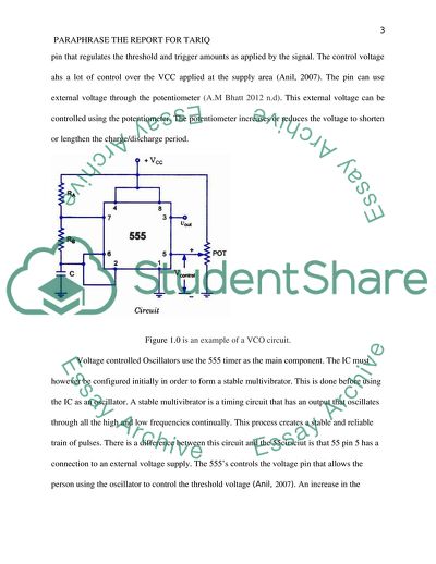
PARAPHRASE THE REPORT FOR TARIQ PARAPHRASE THE REPORT FOR TARIQ PART 4 Experiment: designing and testing of a delay unit ObjectivesThis section has objectives that will guide the designing process and testing the delay unit. These objectives include; To conduct experiments on 555 in order to establish the property. Testing and designing a voltage control Oscillator (VCO) To develop and build a delay unit (555 based) Create a trigger circuit. Theory of Experiment The voltage Controlled Oscillator is a module that has the potential to make frequencies that are can be heard by human beings. These frequencies are within the average hearing range of human beings and thus the sound can be received by the human ear. The Voltage Controlled Oscillator enables the person receiving the sound frequencies to regulate the pitch source. The VCO is likened to a guitar string that has the ability to give a specific tone when a string is plucked. A VCO comes with an IV/ OCT CV input that comes from the keyboard controller unit. The CV is responsible for changing the pitch given just like in the case of the guitar. The VCO converts a voltage into a frequency and this role makes its role to stand out. The input can be regulated by the amount of voltage input. The pin 5 terminal of a VCO acts as a voltage control pin that regulates the threshold and trigger amounts as applied by the signal. The control voltage ahs a lot of control over the VCC applied at the supply area (Anil, 2007). The pin can use external voltage through the potentiometer (A.M Bhatt 2012 n.d). This external voltage can be controlled using the potentiometer. The potentiometer increases or reduces the voltage to shorten or lengthen the charge/discharge period. Figure 1.0 is an example of a VCO circuit. Voltage controlled Oscillators use the 555 timer as the main component. The IC must however be configured initially in order to form a stable multivibrator. This is done before using the IC as an oscillator. A stable multivibrator is a timing circuit that has an output that oscillates through all the high and low frequencies continually. This process creates a stable and reliable train of pulses. There is a difference between this circuit and the 55cirsciut is that 55 pin 5 has a connection to an external voltage supply. The 555’s controls the voltage pin that allows the person using the oscillator to control the threshold voltage (Anil, 2007). An increase in the voltage at pin 5 reduces the level of output while decreased voltage increases the level of frequency at the output. Equipments and components used: Equipment: Digital Multi-Meter (DMM), Oscilloscope Breadboard, DC Power Supply Unit (PSU), Components: Capacitors (F): 10n, 22n 100μ (Tantalum), Chips: Resistors (Ω): 330kΩ, 200k, 5×100k, 2×5.1k, 1k, 82, LMC555CN), LEDs: LED, Switch: On/Off Switch Figure 1.1: a 555 timer based VRO Experimental procedure 555-based oscillator was designed and built on a breadboard as shown figure 1.3 Figure 1.3: A VRO circuit V2 and Vout of maximum and minimum values were recorded with their durations. The observations after increase in RA to 330 kΩ was noted and recorded. The supply voltage was reduced to 6V while RA was set equally to RB=100kΩ. Test 1 was repeated and outcomes observed. A reduction of the supply voltage to 8V was done and the test repeated. V5 was set to 0-8V and the Vcc was set to 9V. Pin 5 was set to 5V. Recording of the minimum and maximum values of V2 and Vout took place. A graph of V2 (Maximum), V2 (Minimum), Vout (Maximum), and frequency against V5 was plotted. Results and discussion Discussion questions A comparison of waveform Vout and Vc is based on the NOR gate based oscillator. The observations made revealed that the waveform of 555 timer oscillator is square while that of the NOR gate was a triangular wave. Additional observations further reveals that the increased value of RA made the amplitude of waves to increase according to an increase in the resistance value. The observations further show that the voltage increased from 2.8 V to 10V. Setting RA to 100 kΩ and RB to 330kΩ. the duration for Vout=’high’ reduction from 2.98ms to 1.386ms while the Vout=’low’ rate remains constant. When RA was set to be equal to RB=100kΩ and the supply voltage was reduced to 6V, then the Maximum voltage= 7 V, minimum voltage= -200mV Tests 3 and 4, direct the study to the following deductions on the relationship between the between the values below: When V2 is set to the maximum– Vcc is inversely proportional to V2 When V2 is set to the minimum–- Vcc is directly proportional to V2 When Vout is set to the maximum– Vcc is directly proportional to Vout. GRAPHS Discussion on frequency changes The changes in frequencies are notable and the explanation is because the changes in voltage affect the impendence of the circuit. This means that the capacitance is changed and thus the frequency is inversely proportional to the capacitance. The equation below relates to the statement 1/ (1.386R2*C) PART 5: Putting together and calibration Objectives To create an interface for the delay unit, the amplifier and the oscillator Develop a calibration for the system To enforce practical skills To develop a theory for the experiment. Oscillators An oscillator is a circuit that has the ability to generate oscillating sine waveforms, electronic signals and periodic signals. Oscillators convert direct current from the source to alternating currents. Different electronic devices can be used as oscillators. Examples of signals produced by oscillators include radio signals, computer clock signals, clock circuits, television signals among others. Computer games and electronic beepers give off sounds that are likened to oscillation signals. Components and equipment Equipment: Breadboard, DC Power Supply Unit (PSU), Battery: 9V with connectors, Digital Multi-Meter (DMM), Oscilloscope, Screwdriver Components: Resistors (O): 10k, 300k, 5×620k, Capacitors (F): 33µ, Potentiometer (O): 50k Linear Carbon, Multi-position switch NB: Resistors are 0.25W Metal Film (: 1%) EXPERIMENTAL PROCEDURE 1. Interfacing The connection of the delay unit to the oscillator is indicated in the figure 2. Calibration a. The figure indicates the connection of the potentiometer b. The delay was set to 1min For R3=620kΩ. 3. The testing for the delay was recorded at every value of R3. The circuit given in fig. 5.3 was built using a multi-position switch 4. A 9V battery replaced the power supply unit and the observations made. Results and discussion Delay(min) 0.5 1 2 3 4 5 R3(k) 310 620 1240 1860 2480 3100 Discussion questions Q1: Disabling the NOR gate, what should be the level of the control signal? ‘high’ or ‘low’? (Hint: Explore the properties of NOR gates for guidelines) Answer: A high control unit should be used for disabling purposes. Q2: Before the required delay is reached, what is the expected output of the delay unit (pin 3 of 555) Answer: Vout=9 V 4. Q1: What I the use o a C5 in a circuit? 5. The capacitor ensures that there power connection is constant for charging and discharging at different intervals. 6. Q2: What is the importance of using two switches (S1 and S2)? 7. Answer:S2 is a safety switch is a back up that protects the components in case of any malfunction. S1 is the systems switch and it is important in switching on and off based on status of the capacitor. Conclusion The voltage controlled oscillator was developed and tested by doing various procedures in the experiment. The properties of how different parameters change relative to others were observed in designing the VCO, and this has strengthened our practical skills on 555 timer based oscillators. Also comparison showed that the waveform for 555 timer based oscillator is rectangular in shape while that of a NOR gate-based oscillator is a triangular wave. The voltage controlled oscillator came about as a result of conducting different procedures. The experiments recorded how different parameters transformed with relation to other aspects when designing the ideal VCO. This observation was important as it strengthened the practical and intellectual skills on the 555 timer based oscillators. Comparing the oscillators also revealed that 555 timer based oscillators assumes a rectangular shape while the NOR gate takes a triangular wave. References Anil K. Maini 2007, Digital Electronics, Principle, Devices and Application, John Wiley and Son Limited, England Read More
Cite this document
  • APA
  • MLA
  • CHICAGO
(Designing a Voltage Control Oscillator Report Example | Topics and Well Written Essays - 1250 words, n.d.)
Designing a Voltage Control Oscillator Report Example | Topics and Well Written Essays - 1250 words. https://studentshare.org/engineering-and-construction/1873156-paraphrase-the-report-for-tariq
(Designing a Voltage Control Oscillator Report Example | Topics and Well Written Essays - 1250 Words)
Designing a Voltage Control Oscillator Report Example | Topics and Well Written Essays - 1250 Words. https://studentshare.org/engineering-and-construction/1873156-paraphrase-the-report-for-tariq.
“Designing a Voltage Control Oscillator Report Example | Topics and Well Written Essays - 1250 Words”. https://studentshare.org/engineering-and-construction/1873156-paraphrase-the-report-for-tariq.
  • Cited: 0 times

CHECK THESE SAMPLES OF Designing a Voltage Control Oscillator

Voltage

If the RMS voltage of the mains is 240V, find the RMS value of the current flowing in the fire and the peak values of current and voltage.... Due to a fault on the mains supply, the peak voltage surges instantaneously to 1000V.... Peak voltage would be 339.... At a peak voltage of 1000 volts, the fire would draw 17....
3 Pages (750 words) Research Paper

Wirless Transformer Charger

The DC voltage will be obtained by the feeding and conversion of the unipolar signal into low pass filter.... To lessen the undulation of the DC voltage, the application of the voltage regular is done, which results in the formulation of a flat DC voltage capable of turning on the switch....
5 Pages (1250 words) Essay

Lab report in DC Voltage Regulators

A linear voltage is regulator is often used to create a known voltage using a transistor which operates in the regulator's forward active… a voltage regulator can therefore be defined as a gadget which creates an output voltage which is steady, clean and of known value under varying conditions including load impedances/load currents, varying Typically, Zener diodes are intended to offer constant output voltage to a given load connected parallel to it irrespective of the variations in voltage supply or load current fluctuations....
5 Pages (1250 words) Assignment

Parphrase for ibrahim

The 555 timer based oscillator is actually a specific type of circuit that produces high intensity based and swiftly moving waveforms.... The circuit so obtained makes up for a particular form of flexible oscillator that produces square waveforms which themselves are relatively static in their outlook.... In contrast to the mono stable set of circuits which halts its movement through the course of given time is lapsed, oscillator circuit at hand enables the function of re-triggering mechanism obtained through the meddling of the trigger input pin Number two along with the given sixth Pin that are explained above and each operating to a specific threshold voltage....
6 Pages (1500 words) Essay

Acoustic Wave and Electromechanical Resonators Concept to Key Applications

I… Finally, many thanks goes to my family as a whole for their valuable time that they offered to me during the entire project period The source of the signal that the system uses is termed as the Gunn oscillator, which is at a signal of 10.... The output power may as well be varied by varying the voltage supplied that is received by the Gunn oscillator via the unit cable attached to it (Campanella 2010)....
7 Pages (1750 words) Essay

Quantum Oscillator Problem

The quantum oscillator wave functions are given in equation 6.... The quantum oscillator wave functions are given in equation 6.... This is a quantum oscillator problem.... The quantum oscillator wave functions are given in equation 6....
1 Pages (250 words) Assignment

Introductory Control: First Order System Response

"Introductory control: First Order System Response" paper contains a comparison of the system response for different values of α, evaluation of steady-state value yss of system output for the different values of α used, and examines values of α for which the system stable....
9 Pages (2250 words) Assignment

El Nio-Southern Oscillation

… The paper "El Niño-Southern Oscillation" is an outstanding example of an assignment on environmental studies.... Many people understand that the term El Nino is associated with floods around the world.... This is one part of what is called El Nino Southern Oscillation or ENSO.... This phenomena usually happens in the tropical part of the Pacific Ocean, and the full event happens about every five years or so....
1 Pages (250 words) Assignment
sponsored ads
We use cookies to create the best experience for you. Keep on browsing if you are OK with that, or find out how to manage cookies.
Contact Us