StudentShare
Contact Us
Sign In / Sign Up for FREE
Search
Go to advanced search...
Free

Microelectronics and Two Major Infrastructures: Photolithography and Particle Beam Lithography - Research Paper Example

Cite this document
Summary
The paper describes the number of complex processes and activities that make photolithography possess. Photolithography involves a series of steps from wafer cleaning to hard-baking. Photolithography involves the process of transferring geometric shapes on a mask to the surface of a silicon wafer…
Download full paper File format: .doc, available for editing
GRAB THE BEST PAPER96.7% of users find it useful
Microelectronics and Two Major Infrastructures: Photolithography and Particle Beam Lithography
Read Text Preview

Extract of sample "Microelectronics and Two Major Infrastructures: Photolithography and Particle Beam Lithography"

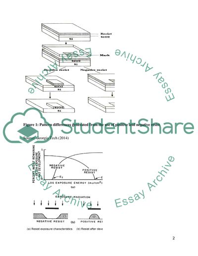
Through conventional lithography, microelectronics has come out with two major infrastructures that are generally accepted in literature for patterning nanoscale features. But to make the use of the infrastructure possible, Savile (2008) advocates the use of two major methods, which are photolithography and particle beam lithography. Georgia Tech (2014) explains that, photolithography involves the process of transferring geometric shapes on a mask to the surface of a silicon wafer. As simple as the definition may sound, there are a number of complex processes and activities that make photolithography possess. For example, Rodgers (2006) posited that photolithography is the standard method involved in microprocessor fabrication and print circuit board (PCB). Photolithography involves series of steps from wafer cleaning to hard-baking to achieve a complete process. As indicated in fig. 2, Savile (2008) noted that at the development stage, there could be negative resist or positive resist, depending on the outcomes of positive and negative photoresist as showed in fig. 1. Figure 1: Pattern differences generated from the use of positive and negative resist Source: Georgia Tech (2014) Figure 2: Response curves for negative and positive resist after exposure and development Source: Georgia Tech (2014) Unlike photolithography which may be noted to be a high process, Gates et al. (2005) identified beam lithography to be a slow process when compared to photolithography. Beam lithography has however been noted to be an instrumental method in the production of high-resolution with that require arbitrary patterns. Two nm resolutions come together to form three main classes of scanning beam lithography. These nm resolutions are ~250nm resolution and sub-50 nm. Out of these, Gates (2005) found three classes known as scanned laser beams, which uses the ~250nm resolution, and focused electronic beams and focused ion beam (FIB), which uses the sub-50 nm resolution. Of the three however, Souza et al. (2010) noted that FIB is the most extensive, most used and most advanced class of scanning beam lithography that is used for high-resolution photomasks. On their part, Gates et al. (2005) maintained that for FIB to be used in high-resolution photomasks, they ought to be patterned by use of laser writers and electron-beam tools. Nanofabrication by Molding and Embossing Molding and embossing are also methods of nanofabrication that are often used together and hand-in-hand to achieve the same outcome. This notwithstanding, Dvir, et al. (2011) noted that molding and embossing are not exactly the same things. With this noted, Gates et al (2005) defined molding as involving “curing a precursor against a topographically patterned substrate” (p. 1175). Embossing on the other hand has been said to involve the transfer of mold based on structured topography that have been produced from a flat polymer film (Kim, 2010). To use molding and embossing as a combined method for patterning nanoscale structures, Saini, Saini and Sharma, S. (2010) has explained the need to devise the procedure that is tangential for both methods. It is based on this that Gates et al (2005) found two workable techniques in molding and embossing, which are molding and embossing of nanostructures with a hard mold and molding and embossing of nanostructures with a soft mold. The practice of molding and embossing of nanostructures with hard mold has been explained by Saini, Saini and Sharma, S. (2010) to be also known as hard pattern transfer element. Hard pattern transfer elements involve any transfer of patterned topography into either a monomer, pre-polymer or complete polymer substrate (Binnig and Rohrer, 2006). To achieve this state of hard pattern transfer, series of techniques, some of which has been identified by Drexler (2012) to include relief printing and injection molding are used. There are several commercial use of hard pattern transfer as noted by Gates et al (2005) to include patterning of compact discs, digital versatile discs, holographic grating, and plastic parts. Figure 3 gives an illustration of hard pattern transfer through the use of stamps. Figure 3: Hard Pattern Transfer using Stamps Source: Gates et al. (2005, p. 1177) When molding and embossing of nanostructures with a soft mold takes place, it is said that soft pattern transfer is being used (Wolfgang, 2003). Gates et al. (2005) argued that soft pattern transfer involves casting a liquid polymer precursor against a topographically patterned master” (p. 1177). A soft pattern transfer by use of a master is depicted below. Figure 4: Soft Pattern Transfer using Master Source: Gates et al. (2005, p. 1177) Even though molding and embossing may be generally regarded as effective methods of nanofabrication, there are key limitations that make other methods preferable to them. Binnig and Rohrer (2006) for example touched on the fact that molding and embossing often produce resolution that are limited by several factors. Consequently, Gates et al (2005) identified some of the factors to include the fact that fabricating of masters is sometimes not practicable; most materials do not mold with high fidelity; distortion of features; monomers causing master to swell; and inability of molded materials to fill mold completely. Nanofabrication by Printing Gates et al. (2005) observed that when given a topographically patterned stamp, it is possible to undertake nanofabrication through the transfer of material onto a substrate by printing. This is where nanofabrication by printing is said to have taken place. To achieve this process, the formation of covalent bonds is required as noted in Allhoff, Lin and Moore (2010). For most developers, the use of a process called microcontact printing (μCP) is preferred. Microcontact printing has been explained by Drexler (2012) to be a type of soft lithography. Allhoff, Lin and Moore (2010) however sees a key difference in microcontact printing from other forms of soft lithography in the fact that mircocontact printing, there is the use of relief patterns on a master polydimethylsiloxane (PDMS) stamp in the formation of patterns of self-assembld monolayers (SAMs). Describing further, Gates et al. (2005) noted that it is at the point where there is the involvement of PDMS that transfer of molecules takes place. As a result, transfer of molecules from the patterned PDMS stamp leads to the formation of covalent bonds. Nanofabrication by printing has been used extensively in both commercial quantities and for the purposes of personal laboratory experimentation. Fields such as cell biology, surface chemistry and microelectronics have all used this method of nanofabrication very extensively (Davidson College, 2010). Figure 5: Electric Microcontact Printing Source: Gates et al. (2005, 1182) Microcontact printing may take place in many forms, including electrical microcontact printing nd nanotransfer printing. In the figure above, a schematic illustration of electrical microcontact printing is given, where in (A), there is a Kelvin probe force microscopy (KFM) measurement of the film provided. In (B), there is a state of no change, while in (C), a positive ring charge is achieved with full-width half-maximum of ~135nm. As a form of soft lithography, Georgia Tech (2014) noted that there are a number of limitations that hinder the use of printing as a method of nanofabrication. Of these, Gates et al. (2005) mentioned “minimum size of features in the stamp; lateral dimensions and resolution of transfer material; and preferential adhesion of the printed material to the second surface” (p. 1182). Scanning Probe Lithography (SPL) In literature, various writers continue to debate about the place of scanning probe lithography in nanofabrication. This is because even though SPL has been accepted by most as a scientific and researchable area in method of nanofabrication, the concern for most others is that SPL still requires a lot of development to be used in the patterning of large areas in manufacturing (Lubick and Betts, 2008). In other words, SPL only remains a scientific and academic method but not a practical method that yield industrial results. As an independent method of nanofabrication, SPL has been explained to be the process of manipulating and imaging the topography of a surface using an atomic-scale resolution (Rodgers, 2006). To make SPL functional at the experimental level, there are a number of techniques that must be fulfilled or followed. Gates et al. (2005) three of these techniques to include STM, which is scanning tunnelling microscopy, after which there is atomic force microscopy or AFM, and then finally near-field scanning optical microscopy (NSOM. As showed in the figure below, when applied effectively by precisely positioning individual iron atoms with an STM tip, it is possible to achieve optimum outcome of SPL for nanoscale. Figure 6: Schematic Representation of 2 Approaches of SPL Source: Gates et al. (2005, p. 1184) In the figure above, there is a schematic representation of two approaches of SPL and the patterns that result in their production. For example, in (A), there is a STM which has been used to position atoms on a high precision surface. The result of this process is what has been achieved in B as a quantum corral of 48-atom Fe ring which has been formed on a different surface of Cu. Fabrication of High aspect ratio pillars by two-photon polymerisation techniques Fabrication of micro bristles A very unique characteristic of micro bristles identified by Yang et al. (2013) is the highly uniform hole spacing that they possess. This characteristic has been explained by Drexler (1986) to be present based on the template used in the fabrication of the micro bristles. What this means is that the technique of fabrication as well as template used in the fabrication is very important to achieve outcomes with the overall function of micro bristles, especially when it comes to the uniformity of their hole spacing. But even to aspire for the attainment of highly uniformly hole spacing in micro bristles, it is important to understand processes and techniques that brings about the achievement of a workable micro bristle. In the opinion of Feng (2009), the fabrication of micro bristles is a critical approach in constructing different forms of micro bristles. Through the fabrication, Dickey et al. (2007) observed that it is possible to form micro bristles in a spontaneous manner across a narrow capacitor gap when an electric field is applied to any normal to thin fluidic film (p. 117). When fabrication of micro bristles is performed in this manner, it is generally commended to have an outcome that is appealing because it is possible to achieve the formation of micro bristles in a very rapid and inexpensive manner (Chatterjee, 2007). This merit notwithstanding, Yang et al. (2103) saw several lapses with the use of such fabrication methods where there is emphasis only on applying electric field to fluidic film. For example, it has been argued that the resulting micro bristles are most of low aspect ratios as showed in the diagram below. Figure 7: Tilt View of Low-aspect ratios Polymeric Pillars Source: Dickey et al. (2007, p. 118) The Role of two-photon polymerisation techniques In the figure above, the best that was achieved was a ~0.1 low-aspect ratios when the polymer pillar was formed by use of 40V, 2.5µm gap, and 800 –nm film. Because of the weakness of the process identified above, fabricators have continued to look for more ideal ways of achieving simple fabrication of micro bristles that can have high aspect ratio. The use of two-photon polymerisation techniques have been deemed by many as the best way forward for the fabrication of high-aspect ratio pillars (Ostendorf and Chichkov, 2006). Ovsianikov et al. (2007) explained the two-photon polymerization, often referred to as 2PP as a novel CAD/CAM technology that enables the fabrication of any computer-designed 3D structure from a photosensitive polymeric material. In effect, the functioning of 2PP is largely based on the presence of a computer-designed 3D structure activity. In a much generalised explanation, Ostendorf and Chichkov (2006) noted that the reason this technique works best is that it they can easily possess femtosecond lasers that achieve microfabrication with resolutions that are far beyond the diffraction limit that most conventional techniques have. According to Ovsianikov et al. (2007), when used in the fabrication of micro bristles and for that matter polymeric pillars, it is possible to achieve high-aspect ratios because the two-photon polymerization works with ultrashort laser pulses that guarantees three-dimensional mircofabrication outcomes. Explaining the precise methodology behind the technique, Ostendorf and Chichkov (2006) explained that the ultrashort laser pulses that are present initiate two-photon polymerisation through two-photon absorption and subsequent polymerisation. The guarantee of high-aspect ratios thus comes from the fact that there is not just a single polymerisation but a subsequent one as well. In Yang et al (2013), there was a vivid outcome of what the result of a high-aspect ratio production of micro bristles would look like when subjected to the use of two-photon polymerisation technique. Figure 8: Schematic Diagram of Micro Brushes Source: Yang et al. 2013 Nanotechnology in tissue engineering Nanotechnology has advanced to such a stage that it is now being used in medicine in what is called nanomedicine (Gates et. al., 2005). According to Shi, Votruba, Farokhzad, and Langer (2011), nanomedicine comes in several types and forms, including tissue engineering. Dickey et al (2007) explained a number of complexities that go into the formation tissue engineering. First of all, nanotechnology has been found to be used as a platform for designing and fabricating biocompatible scaffolds at the nanoscale (Shi, Votruba, Farokhzad and Langer, 2011). Shi et al. (2011) further cautioned that this design and fabrication must however be done at the control of the fabricator, who takes charge of the spatiotemporal release of biological factors, which includes the resembling of native extracellular matrix. Once this process is followed, it is possible to direct cell behaviours so as to achieve the creation of implantable tissues. On their part, Dvir et al. (2011) explained that the use of nanotechnology in tissue engineering has been used with the motivation of repairing damage tissues and organs. Until this motivation was achieved, nanotechnology in the creation of tissue engineering was focused on tissues boundaries with the extra-cellular matrix (ECM). But even today, ECM plays very instrumental role in the formation of tissue engineering by focusing on the ECM’s topography, mechanical properties, growth factor concentrations and ECM molecules. In Dvir et al. (2011), the ECM is seen to possess properties that promote a unique microenvironment that fosters tissue organisation. This tissue organisation thus serves as the basis of designing and fabrication of biocompatible scaffolds that leads to tissue engineering. The preparation of scaffold with micro bristle on them to do cell culturing is very instrumental in tissue engineering (Lubick and Betts, 2008). There are three major design examples commonly identified with the deigning of a scaffold. The first of these is the use of scaffolds in cardiomyocytes, which is achieved as ECM forces cardiomyocytes to couple mechanically (Dvir et al., 2011). It would be noted that the cardiomyocytes is a term that is used to generally refer to the muscle cells that constitute the cardiac muscle (Wolfgang, 2003). On the part of Kim (2010), it is possible to achieve the alignment of cells in this same way by the use of nanogrooved surface instead of using ECM. Scaffolding and for that matter tissue engineering has also been found to be useful in epithelial cells. These epithelial cells are noted to be the most prolific among the four major tissues found in the human body (Davidson College, 2010). Generally, the epithelia are formed from cells that line the cavities in the body and other flat surfaces in the body. According to Feng (2009). To use tissue engineering on epithelial cells, the cells must be polarised to adhere to other cells. On their part, Dvir et al. (2011) debated that the same effects can be achieved when nanofibres are modified with surface molecules. Lastly, tissue engineering and scaffold are largely used in the bone. The effect in bones is generally made possible through osteoblasts, which are influenced by bone matrix. Already, Goodman, et al. (2005) had observed that it is possible to use nanostructures to enhance osteogenesis. Once this is done, the influence by the bone matrix becomes achieved. This last process is depicted in the diagram below. Figure 9: Using Nanostructure to enhance Osteogenesis Source: Dvir et al. (2011). In all of these processes, cell culture is very instrumental. This is because just as nanotechnology depend on the manipulation of matter on atomic, molecular or supramolecular scale (Drexler, 1986), cell culture also demands the use of manipulative principles outside of the natural environment cells. This is because Chatterjee (2007) explained that cell culture is the process by which the growth of cells is put under the control of conditions that are outside the natural environment of cells. When cell culture is employed in any of the designs of scaffolds as reviewed earlier, there are a number of advantages that are recorded. For example, with the advancement in nanomedicine, cell culture has been noted to be very crucial in drug discovery that are related to any of the design examples given earlier. The reason the result of cell culture in these designs is important and different from other methodology is that in cell culture, there is the production of two-dimensional cell growth with gene expression, signaling and morphology (Souza et al., 2010). These two-dimensional cell growths are said to be superior to those found in vivo as these cell growth are made up of their clinical relevance (Goodman, 2005). What is more, there are three-dimensional tissue culture based on magnetic levitation of cells which give much advanced relevance and importance. A typical example of such three-dimensional tissue culture is those produced by Souza et al (2010) using the presence of hydrogel consisting of gold, magnetic iron oxide nanoparticles and filamentous bacteriophage. The merit of such three-dimensional cell culture product is that they are considered more feasible for long-term multicellular studies (Souza et al., 2010). Supercritical CO2 drying process of 3-D microstructures For most of the nanotechnology and nanofabrication processes that have been considered such as two-photon microfabrication, tissue engineering and fabrication of micro bristles, there is the need for drying. As options for drying abound, Maruo, Hasegawal and Yoshimura (2009) recommend the use of supercritical CO2 drying. Generally drying is needed due to the activity of surface tension, leading to the possible collapse of nano structures. Apart from the need to control surface tension and such other processes, Maruo, Hasegawal and Yoshimura (2009) noted that supercritical CO2 drying process actually bring about enabled high-precision microfabrication of three-dimensional structures such as micro bristles. Generally, Maruo, Hasegawal and Yoshimura (2009) identified three major variations of drying processes. The first of these were between natural drying and supercritical CO2 drying of micropillar arrays. In both cases, the researchers applied the fabrication of 10-μm-high pillar array with diameter of 1μm. Once this was done, the resulting outcome as showed from a scanning electron microscope (SEM) images was that there was a collapse of the pillars for the natural drying due to the activity of surface tension at the point that the rinse was evaporating. This was however not the case for the supercritical CO2 drying as no collapse of pillars took place here. The differences that were produced in the two variations of drying has been depicted in the diagram below. Figure 10: Drying with (a) Natural Drying and (b) Supercritical CO2 Drying Source: Maruo, Hasegawal and Yoshimura (2009, p. 430). The outcome of the experiment above shows the potential and characteristic of supercritical drying in maintaining the structures of micro bristles. Conversely, the weakness of natural drying is also highlighted. The result of Maruo, Hasegawal and Yoshimura (2009) has been furthered in other studies that have sought to understand the characteristic nature of drying process that would make it suitable for use with other methods of drying. In one of such studies, Scarberry, Dickerson, McDonald and Zhang (2008) tested the use of single-anchor supporting method. The notion of this was to remove all forms of non-uniform shrinking of polymeric structures that were formed as part of the fabrication process. The single-anchor supporting method turned out to be one of the most effective. This is because while trying to get rid of the resultant products of attached substrates which were the polymeric structures, it came out that there was a permissible frame model that supported the production of lattices in the polymeric structure formation. Meanwhile, Fresnais, Lavelle and Berret (2009) were very confident that the lattice that was produced from the drying process produces no sequential harm in the form of distortion to the micro bristles. From this basis, it can be noted that the single-anchor supporting method is as effective as the supercritical CO2 drying process but the same cannot be said for the natural drying process. Based on the outcome of the single-anchor support method, Maruo, Hasegawal and Yoshimura (2009) actually suggested the combination of this method with the CO2 drying process. This is because in their opinion, the combined drying process guarantees reliable high precision microfabrication. What is more refreshing is that when the combined process is used it gives rise to high precision in all forms of mircorfabrication including the most sophisticated and fragile nanostructures (Maruo, Hasegawal and Yoshimura, 2009). 5- use of magnetic nanoparticle to actuate microbristles Very often nanoparticles are subjected to manipulation by the use of magnetic field. Once this is done, the resuting outcome is a magnetic nanoparticle formation (Colombo et al., 2012). Fresnais, Lavelle and Berret (2009) observd that due to the action of the magnetic field on the nanoparticle, there is always a remained effect of magnetic elements on the magnetic nanoparticles. Some of these magnetic elements include both the natural states of nickel, cobalt and iron, and the chemical compounds of these elements. In most modern studies in nanofabrication, there has been particular emphasis on magnetic nanoparticles. This is largely due to the unique characteristics possessed by these. According to Digbel et al. (2011), magnetic nanoparticles actually have properties that makes it possible for them to function differently from ordinary nanoparticles. Most of these ordinary nanoparticles have often had diameters that are less than 1 micrometer but Colombo et al. (2012) argued that magnetic nanoparticles have extended diameters that make their potential use in catalysis possess. What is more, nanoparticles have been found to be effective to actuate microbristles. In such a state, Digabel et al. (2011) posited that a magnetic actuated mircobristles is said to be formed. These magnetic actuated microdevices are said to have several functions and importance in microfluids and microfabrication that their use is have been preferred in several areas including magnetic particle imaging, nanomaterial-based catalysis, nanofluids, defect sensor, optical filters and so many other functions (Digabel et al., 2011). Having noted the functional roles that magnetic actuated microdevices including actuated microbristles can play, Sniadecki et al. (2007) noted that it takes much work in handling the creation of magenetically actuated microbristles. This stage of strategic creation must actually be crossed before any benefits can follow. In this, Digabel et al. (2011) used a combined strategy made up of microfabrication techniques and the dispersion of magnetic aggregates embedded in polymeric matrices. Through this, it was possible to induce the presence of micrometre scale magnetic characteristics in the microbristles (Parera, Kouki, Finne and Pieters, 2010). The creation of the magnetic field is considered by many as a first approach to gaining an actuated microbristle because in the case of Digabel et al. (2011), the presence of the magnetic field gradient made it possible for there to be the induction of deflected micropillars. Meanwhile, the said induction is considered the best approach to gain actuations within range of dimensions necessary to offset any relevant applications such as those mentioned earlier and others like microfluids and other biological applications (Digabel et al. 2011). Touching on the potential of magnetic microposts, Sniadecki et al. (2007) actually indicated that these can be used as a method of applying force to living cells to actuate them to respond to clinical experiments. References Allhoff, F, Lin, P. and Moore, D. (2010). What is nanotechnology and why does it matter?: from science to ethics. John Wiley and Sons: New York. Binnig, G.; Rohrer, H. (2006). "Scanning tunneling microscopy". IBM Journal of Research and Development 30: p. 4. Chatterjee, R (2007). "Cell biology. Cases of mistaken identity". Science Vol. 315 No. 5814: 928–31. Colombo M et al. (2012). Biological Applications of Magnetic Nanoparticles. Chem Soc Rev; Vol. 41 No. 11: pp. 4306-34 Davidson College (2010). Overview of Epithelial Cells. [Online] Available from http://www.bio.davidson.edu/people/kabernd/berndcv/lab/epithelialinfoweb/index.html [April 5, 2014] Dickey G. et al (2007). “High-aspect ratio polymeric pillar arrays formed via electrohydrodynamic patterning: J Mater Sci. 43: pp.117–122 Digbel J. et al. (2011). “Magnetic micropillars as a tool to govern substrate deformations”. Lab Chip. Vol. 11 No. 4, pp. 2630. Drexler, K. E. (1986). Engines of Creation: The Coming Era of Nanotechnology. Doubleday. Vol. 43 No. 2, pp. 324-432 Drexler, K. E. (2012). Nanosystems: Molecular Machinery, Manufacturing, and Computatin. John Wiley & Sons: New York Dvir, Tal, et al. (2011). Nanotechnological strategies for engineering complex tissues. Nature Nanotechnology. Vol. 23 No. 2, pp. 234-249. Feng, ZQ. (2009). The effect of nanofibrous galactosylated chitosan scaffolds on the formation of rat primary hepatocyte aggregates and the maintenance of liver function. Biomaterials. Vol. 23 No. 2, pp. 44-45 Fresnais J., Lavelle C. and Berret J. F. (2009), “Nanoparticle aggregation controlled by desalting kinetics” J. Phys. Chem. C, 113, 16371–16379. Gates Y. et. al. (2005). “New Approaches to Nanofabrication: Molding, Printing, and Other Techniques” Chem. Rev. 105, pp. 11711196 Georgia Tech (2014). Photolithography. [Online] Available at http://www.ece.gatech.edu/research/labs/vc/theory/photolith.html [8th April, 2014] Goodman, R.P. et al. (2005). "Rapid chiral assembly of rigid DNA building blocks for molecular nanofabrication". Science Vol. 310 No.5754: pp. 1661–1665. Kim, DH. (2010). Nanoscale cues regulate the structure and function of macroscopic cardiac tissue constructs. PNAS. Vol. 35 No. 23, pp. 323-294. Lubick N and Betts, K. (2008). "Silver socks have cloudy lining". Environ Sci Technol Vol. 42 No.11: pp. 3910. Maruo S., Hasegawal T. and Yoshimura N. (2009). Single-anchor support and supercritical CO2 drying enable high-precision microfabrication of three-dimensional structures. Optic Express. Vol. 17, No. 23 423-455 Ostendorf A. and Chichkov B. N. (2006). Two-Photon Polymerization: A new Approach to Micromachining. Spectra. Vol. 40 No. 10, pp. 72-80. Ovsianikov A. et al. (2007). Two-photon polymerization technique for microfabrication of CAD-designed 3D scaffolds from commercially available photosensitive materials. J Tissue Eng Regen Med, 1: 443–449. Parera Pera N, Kouki A., Finne J., Pieters R. J., (2010). "Detection of pathogenic Streptococcus suis bacteria using magnetic glycoparticles". Organic & Biomolecular Chemi Vol. 8 No. 10: 2425–2429. Rodgers, P. (2006). "Nanoelectronics: Single file". Nature Nanotechnology. Vol. 43 No. 2, pp. 24-64 Saini, R, Saini, S., and Sharma, S. (2010). "Nanotechnology: The Future Medicine". Journal of Cutaneous and Aesthetic Surgery Vol. 3 No.1: pp. 32–33. Savile B. B. B. (2008). Introduction to Light Microscopy; BIOS Scientific Publishers Ltd: Oxford, U.K. Scarberry K.E., Dickerson E.B, McDonald J.F and Zhang ZJ (2008). "Magnetic Nanoparticle-Peptide Conjugates for in Vitro and in Vivo Targeting and Extraction of Cancer Cells". Journal of the American Chemical Society. Vol. 130 No.31: pp. 10258–62. Shi J., Votruba, A. R, Farokhzad, O. C and Langer R. (2011). Nanotechnology in Drug Delivery and Tissue Engineering: From Discovery to Applications. Nano Lett. 10(9): 3223–3230. Sniadecki et al. (2007). Magnetic microposts as an approach to apply forces to living cells. PNAS. vol. 104 No. 37, pp. 14553–14558 Souza et al. (2010). Three-dimensional tissue culture based on magnetic cell levitation. Nature Nanotechnology 5, 291 - 296 Wolfgang K. (2003). Color atlas of cytology, histology, and microscopic anatomy. Thieme. Vol. 234 No. 43, pp. 172 Yang R. et al. (2103). “Highly uniform hole spacing micro brushes based on aligned carbon nanotube arrays”, Nanoscale Research Letters, Vol. 8 No. 501, pp. 3-242 Read More
Cite this document
  • APA
  • MLA
  • CHICAGO
(“Microelectronics and Two Major Infrastructures: Photolithography and Research Paper”, n.d.)
Microelectronics and Two Major Infrastructures: Photolithography and Research Paper. Retrieved from https://studentshare.org/engineering-and-construction/1818989-laser-based-polymer-structuring-for-tissue-engineering
(Microelectronics and Two Major Infrastructures: Photolithography and Research Paper)
Microelectronics and Two Major Infrastructures: Photolithography and Research Paper. https://studentshare.org/engineering-and-construction/1818989-laser-based-polymer-structuring-for-tissue-engineering.
“Microelectronics and Two Major Infrastructures: Photolithography and Research Paper”, n.d. https://studentshare.org/engineering-and-construction/1818989-laser-based-polymer-structuring-for-tissue-engineering.
  • Cited: 0 times

CHECK THESE SAMPLES OF Microelectronics and Two Major Infrastructures: Photolithography and Particle Beam Lithography

Laser Beam Condensation

Laser beam Condensation affiliation Laser beam Condensation Media article In the media article, the process of condensing gas particles to liquid particles is briefly described.... They include activation of atmospheric particles, ion-induced nucleation, heterogeneous nucleation, homogenous homomolecular nucleation, homogenous heteromolecular nucleation, and the thermodynamics of particle nucleation (Kasparian, Rohwetter, Woste, & Wolf, 2012)....
2 Pages (500 words) Essay

Analysing and responding to the two articles ( comparing bth articles)

Analysing and responding of the two articles Comparison Texting has become a widespread means of communication, today overwhelmingly all the age groups particularly the youth.... SMS abbreviated for Short Message Service has been overpowering almost every one despite of the debate of many people such as John Humphry....
4 Pages (1000 words) Essay

Honore Daumier's Works of Art

Name: Instructor: University: Course: Code: Honore Daumier Honore Daumier was a French national who lived, in France, from 1808 to 1879 when he passed away His life and workings are renowned to this day all around the world.... He was a designer, a painter, a sculptor and a publisher famous for his satirical caricatures of the French government....
4 Pages (1000 words) Essay

Electron Beam Lithography

Electron beam lithography (EBL) is the process of using a focused beam of electrons to form circuit patterns on wafers that are needed for material deposition on them (Silicon Far East 2004).... By controlling these factors, the linewidth can be adjusted to correspond with the requirements of a given circuit. Factors Affecting Linewidth in EBL Electron beam lithography (EBL) is the process of using a focused beam of electrons to form circuit patterns on wafers that are needed for material deposition on them (Silicon Far East 2004)....
2 Pages (500 words) Lab Report

Lithographs from the Collection of Steven Block

The essay "Lithographs from the Collection of Steven Block" states that artistic works done by James McNeil Whistler can be said to be extemporary and that which added aesthetic taste to living.... Construction, interior design can be said to be some of the themes that inspired his work.... hellip; Color and harmony were striking features in his works, and a large scope of his art gave his work a decorative outlook....
1 Pages (250 words) Essay

A current event of chemistry

Mason, who is a professor of chemistry and physics, the scientists sought to find the reason behind such an occurrence using the technique of lithography.... They employed the technique of lithography to manufacture millions of achiral particles in the shape of a triangle.... By this phenomenon, a majority of proteins, like many other molecules in the body, exist in two forms as mirror images of each other.... By this phenomenon, a majority of proteins, likemany other molecules in the body, exist in two forms as mirror images of each other....
2 Pages (500 words) Research Paper

MEMS and Product Design

functional elements comprise miniaturized structures, microelectronics, actuators and sensors, and some of its fundamental components consist of microactautors and microsensors that make up the transducers.... MEMS refers to Micro-Electro-Mechanical Systems.... This is a miniaturised electro-mechanical and mechanical elements such as structures and devices that are made through the use of microfabrication techniques....
4 Pages (1000 words) Essay

Team article review #3

The article written by Stock (2014) is very interesting, especially for my team, because it discusses some of very big issues that hold great importance in the field of business.... It is about competition among businesses, and about who wins and who loses.... Nike has to spend a lot… But, Nike still re-signs him because this will earn the company huge revenue in the days to come, even if it has to lose some of its revenue coming from sales, in hiring Kevin Durant....
1 Pages (250 words) Essay
sponsored ads
We use cookies to create the best experience for you. Keep on browsing if you are OK with that, or find out how to manage cookies.
Contact Us