StudentShare
Contact Us
Sign In / Sign Up for FREE
Search
Go to advanced search...
Free

Aircraft Systems - Essay Example

Cite this document
Summary
This work called Aircraft Systems" describes an approaching aircraft precision, directions for approaching aircraft. The author takes into account air cooling pack or air cycle machine application, the system of pitot-static…
Download full paper File format: .doc, available for editing
GRAB THE BEST PAPER96.7% of users find it useful
Aircraft Systems
Read Text Preview

Extract of sample "Aircraft Systems"

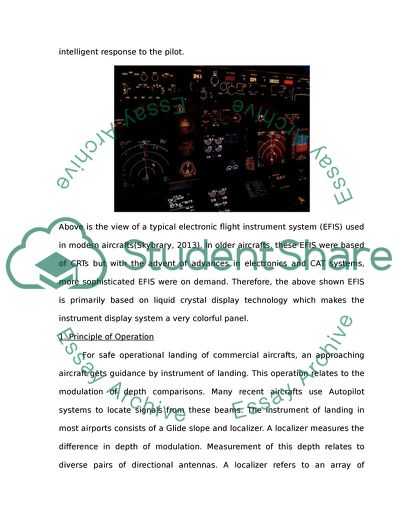
Introduction For commercial Aircrafts to navigate efficiently on the runway various principles and instruments come into action. Various instrumentsare essential for takeoff as well as landing. For typical Commercial aircrafts, radio beam transmitters are important for providing directions for approaching aircrafts. For this principle to function, a pilot needs to tune their receivers to receive airport signals. This beam of signal provides safe lateral and vertical landing signals. An approaching aircraft precision landing depends on high precision landing guidance, which constitutes a combination of high intensity lighting system and radio signals (Nolan, 2010). High intensity lighting systems applies in situations where there is fog, mist and blowing snow discouraging safe landing. Besides, all these active and highly efficient sensory system, modern aircrafts are equipped with state-of-the-art, machine vision and artificial intelligence based versatile and robust systems. All the sensors and actuators used in the navigation panel of the pilot cabin work efficiently due to the CAT (computerized adaptive testing) system. This system is capable of generating a more robust and optimal solution to a problem faced by the navigation system. This system makes the airplanes more autonomous and is capable of communicating and helping the pilots in unexpected situations. CAT systems are not only capable of providing output, but are also provided with built in intelligence to study all the active parameters and provide and intelligent response to the pilot. Above is the view of a typical electronic flight instrument system (EFIS) used in modern aircrafts(Skybrary, 2013). In older aircrafts, these EFIS were based of CRTs but with the advent of advances in electronics and CAT systems, more sophisticated EFIS were on demand. Therefore, the above shown EFIS is primarily based on liquid crystal display technology which makes the instrument display system a very colorful panel. 1. Principle of Operation For safe operational landing of commercial aircrafts, an approaching aircraft gets guidance by instrument of landing. This operation relates to the modulation of depth comparisons. Many recent aircrafts use Autopilot systems to locate signals from these beams. The instrument of landing in most airports consists of a Glide slope and localizer. A localizer measures the difference in depth of modulation. Measurement of this depth relates to diverse pairs of directional antennas. A localizer refers to an array of antennas located beyond the point of departure of the airport. It provides lateral guidance to aircrafts. Typically the system consists of two signal transmitted on one instrument landing system. One of the signals modulations is at 150Hz and 40Hz. The signal is transmission come from co-located antennas where each transmission comes from narrow beam of signals(Britannica, 2013). In every operational landing, the depth of modulation is 20 percent while the difference between the two signals varies in relation to the angle of deviation of approaching aircrafts from the centreline. A Glide slope, on the other hand, provides vertical guidance for pilots. A glide slope refers antennas situated on one side of the runways. These antennas provide signals similar to that of a localizer. The system of glide slope antenna provides a systematic arrangement of glide path at approximately 3° above the landing area (Nolan, 2010). A pilot uses the gliding slope in ensuring that the aircraft remains above the obstruction for safe touchdown. The control system of automatic landing system is shown above(Britannica, 2013). It specifies that flight landing/autopilot system is too exhaustive in terms of adaptive and precise system that it can work while on all airports around the world. The signals from ILS and GPS are processed and displayed on the autopilot control panel in cockpit. This autopilot does not works on its own but keeps on taking input signals from pilots as well. All the signals are given to a specialized relay system which then further switches on or off the output circuits. Difference between flight components and ground components Commercial aircrafts flight system consists of multifunctional systems, flight displays, crew-alerting systems and engine display systems. The flight components of an aircrafts navigational instruments, as opposed to ground components, assist flight engineers detect engine malfunctions that might affect flight, assist pilot locate beams and airports while provide alert for members of the crew. The components also ensure that aircrafts relays and get information from ground sensors. Additionally flight components of CAT navigational instrument consist of display monitors, data processors and control panels for pilots (Jabbal, & Crowther, 2010). Ground components in Paris as well as other airports consist of instrumental landing systems or microwave landing systems. Airports need to have radar altimeter as well as localizers. Pilots despite having Autopilot systems use localizer signals during lateral landing. Some of the instruments displayed in a CAT navigational system include Altimeters Airspeed indicators Altitude indicators. 2. Use of Weather radar Commercial flights occur over diverse climatic regions. Pilots of these Aircrafts have to land in airports with various weather conditions. Some of the airports are prone to fog, mist and other conditions that limit pilots visions. Therefore, there is a need for CAT aircrafts to have weather radar to overcome fog and other elements that might affect pilots’ vision. For commercial aircrafts radar imaging bear blue, red and purple colours. These colors’ intensity relates to winds pressure, prevailing visibility, rainfall and thunder storms. Weather patterns also appear in symbols which indicate to pilots the direction of winds, speed and temperature levels. Airborne radar’s function is to detect thunderstorms and avoid them. This is possible due to the fact the system makes use of radar which detects liquid raindrops by reflective mechanism of radar beams. Most reflective beam indicates wet hail while least reflective beam indicates dry snow. 3-4. Oxygen systems Oxygen system in aircrafts provide supplementary oxygen in a situation of emergency this situation refers to events of smoke, loss of oxygen, fire or in situations of chemical fumes. If cabin pressure is lost during high altitude oxygen masks in front of passengers automatically opens. In cases of emergency passengers do not to get out of their seats so as use the masks. Cabin crew however, may use potable masks since they provide services to passengers in such emergencies. Their masks have to be charged with oxygen in sockets propelled by generators. Flight crew, however, have a separate system of oxygen supply. Due to their tasks flight crew need not to be disoriented by a drop in altitude and probably lose control of the aircraft. Therefore, flight crew in such aircrafts use lavatories oxygen systems. There are two methods of providing oxygen for passengers in aircrafts. The methods are the use of a chemical oxygen generator and by the use of a gaseous manifold system. A gaseous manifold system works by connecting all the masks to a central supply. The supply comes from the cargo area, and it can only be reset from the cockpit or another place in the aircraft. A chemical oxygen generator system on the other hand ensures that pulling of one mask ensures supply of oxygen to all other masks in the compartment. This system comes as a result of chemical reaction between iron powder and sodium chlorate. Two seat military planes travel at very high altitude and have ejection seats (Lovelace, 2012). Therefore, air is pressurized by the engines to ensure that passengers have adequate oxygen a process at times referred to as air bleed. An altimeter is the standard instrument for measuring air pressure. Altitude of aircrafts refers to the measurement of air pressure by use of altimeters. High humidity conditions, as well as frost condition may lead to ice formation on aircrafts either on the ground or on a flight. Ice might form on the wings of the aircraft or on other parts of an aircraft. Therefore, air crew need to detect such conditions. Icing effects on aircrafts might lead to the formation of water droplets on the surfaces of airplanes. Ice might have dangerous implication on the functioning of the jet engine. Icing has an effect of stalling wings of airplanes, as well. Pilots however, have ice detectors planted on the wings of the aircraft to detect ice formation. The device is in the form of a transducer able to relay information to the pilot for further action. To protect airplanes from icing electrical heating system may be used to heat crucial engines of the aircraft in order to prevent ice formation. Aircrafts might also use weeping wings, which has multiple holes, which releases anti icing fluid. The edges of the tail and wings of airplanes facilitates heating of air which evaporates ice on contact a process known as “bleed air”. There are various precautions that one has to undertake to prevent aircraft part from icing. Some of these procedures include avoidance of icing conditions by use of mechanical means, applying de-icing fluid or putting the aircraft of heated hangar (Marwedel & Jörg, 2011). One can even position the aircraft towards sunlight, but if icing persists one has to use ant icing fluids. 5. Aircraft Maintenance and operations Pneumatic system in an aircraft is a very important element in the operation of aircrafts. The system contains air pumps, air filter system and gauge indicators. The system is important since it facilitates exhaustion of air, acts as an air filter, regulates pressure and assists in the failure warning system. The system as other system requires constant maintenance. Signs of failure of this system include contamination, worn out parts, engine stoppage and deceleration. To prevent such incidences one need to install backup systems, regularly check all parts, maintain parts proficiently and use precision instruments for checking. Maintenance of oxygen system, on the other hand, needs to be according to schedule, in line with safety and after maintenance one should dispose waste appropriately. One needs to ensure that all masks are disinfected and proper. Generators need to be maintained and all valves in good working condition. When maintaining the fuel system of an aircraft, individuals should at all time avoid smoking. Maintenance involve cleaning of fuel pumps, tanks, carburettors, injectors and fuel lines (Marwedel & Jorge, 2011) All of these procedures need to be in line with set standards by ATA. CAT Pitot-static system The system of pitot-static consists of sensitive instruments used in the aviation field to determine the altitude of the aircraft, the March speed number, and trend of the altitude as well as airspeed. The system consists of a pitot tube, pitot static devices and static port. The equipment may be connected to flight data recorder, cabin pressurization, airspeed switches or even data recorders (Lovelace, 2012). A representation of the system is as shown below: Part two Airspeed/ vertical speed indicator An airspeed indicator is an instrument in an aircraft that displays the speed of the air plane(MyAirlineFlight, 2009-2013). The instrument relays information to the pilot in terms of knots of the movement of the aircraft. The indicator is used in almost every operation of flight. Its application comes during descend, landing, cruise and take -off. The airspeed works by measuring the difference in static pressure, which is relayed through the pitot tube (Langton, 2009). However, during the performance of this function, the instrument may relay specific errors. Errors attested to the instrument include positional error where the instrument does not calibrate exact positions. Another form of error that occurs while using the instrument is compressibility error. This occurs when the instrument calibrates only standard pressure of the sea. Vertical speed indicators on the other hand measures the rate of climb of an aircraft as well as descend. The instrument operates by detecting change in air pressure as altitude changes. It works by use of airflow. Typically the more the aircraft descends the faster air flows. Air flowing into the air bottle outside the aircraft indicates that the aircraft is descending. In the case where there is a block in reading pilots would not recognize changes. Static readings in aircrafts are important for humans. Unlike birds created for flights pilots would not recognize lifts or descends which might result in unavoidable accidents or loss of life. Air cooling pack or air cycle machine application relates to gas turbine aircrafts. The system is a refrigerated control system on the environment whose components are in two or three parts in almost all aircrafts. The air cooling process uses air instead of changing of materials in phases like gas cycles. The process involves evaporation as well as condensation for cooling equipment. In an aircraft, an ejector pump operates by using its two inlets to pump in gas and motive fluid. These two components move through a nozzle at a given pressure and speed. The system uses the Bernoulli’s principle by increasing pressure as well as decreasing velocity. The resultant effect causes an imbalance resulting to a body to rise (Langton, 2009). 2) Air cycle and vapor cycle cooling system A typical vapor cycle air conditioning system of the aircraft is shown above(IntegratingPublishing, 2014). This air cycle is responsible for controlling air temperature within the aircraft. Typical passenger airplanes usually consist of three air cycles. Two of them are mostly used to cool off the system during cruise fight mode. Whereas in cargo planes there are only two systems to cool off supply air before entering pressurization unit. These air cycles majorly consume bleed air from the engines to be given to the pressurization unit. This bleed air is first passed through the heat exchanger. In heat exchangers ramped air is used to absorb heat energy and cooled air is then transferred to pressurization unit. Ejector pumps are used to eject wastes from the plumbing space of the aircraft and avoid them to move back. These pumps are used to replace gravity as aircrafts may fly at an angle as well. 3) Aircraft Pressurization system The above figure represents a typical CAT based aircraft pressurization system in an aircraft(IntegratedPublishing, 2014). This actually gives the schematic view of all components required to maintain air pressure within the aircraft. Aneroid barometer is mainly used to obtain air pressure at each and every cabin of the aircraft and pitot tube system is also provided within the pilot’s cabin. Purpose of this pressurization system is not only to maintain internal pressure of the aircraft with increasing altitude but it is also responsible for circulating clean and healthy air in passenger cabins of the aircraft. The distribution of air pressurization within the cabins is shown in figure below. An aircraft altitude refers to the height of ascend of the aircraft from the ground at a particular instant during flight, whereas, cabin altitude refers to the cabin pressure(FlightLearning, 2010). At lower heights cabin altitude is usually kept same as external pressure. But as the height keeps on increasing, cabin altitude needs to be maintained. This internal pressure within the cabin is maintained due to a number of reasons and most prominent one is that with the increase in height, pressure within the cabin increases. This increased pressure may damage the humans travelling in the aircraft and may result in physical injuries. This level of aircraft altitude is usually achieved at the height of 8000ft above sea level. Cabin pressurization control depends on the outflow valve which releases pressure to a constant level (Jabbal, & Crowther, 2010). The term rate f climb is actually the change in the altitude or speed of the aircraft. This parameter directly affects the height of aircraft altitude thus cabin altitude as well. At the take-off of the flight, cabin altitude and aircraft altitude are the same. Also the rate of climb of the components is also the same. At this stage, pressurization system of the aircraft is not much active. But as soon as the plane moves beyond the level of 12500 ft, cabin pressure outflow valve get in working mode if the cabin pressure is getting more than a specified limit. In short this outflow valve is a very important component of bleed valve and is used to exhaust increased pressures and vice versa. The term maximum cabin refers to the deferential pressure inside and outside a pressurized aircraft. An example of maximum cabin differential is for the Boeing 787 dream liner that maintains a 6,900ft. 4) Compass and Heading Instrument A compass is a navigational instrument likely found in aircrafts. It gives direction where the pilot is heading. Compass gets power from the aircraft in terms of DC current. The instruments have its setbacks in terms loss of degrees due to other forces making it unreliable. Aircrafts retain magnetic compass, head indicator for emergency reasons. This instruments layout is at the cockpit. In cases of faults CAT has warning captions. These captions include fire bells, configuration warnings, and engine malfunction warnings. The diagnosis of such warning might be to put of fire, repair devices or inform control towers before landing. Sometimes the compass is difficult to read during flight and it may happen due to insufficient information about the earth’s magnetic field as a result of magnetic anomalies. The compass needle may either keep on vibrating or gives a tricky reading. Therefore, pilots take second opinion from a heading indicator present on the side of the compass onboard. The above figure shows the internal structure of heading instrument(GroundInstructors, 2011). This instrument primarilys work on the principle of gyroscope. In this instrument gyroscope is attached to the support that keeps its reference horizontal to the plane of airplane. Therefore any variation in this position is shown on the indicator. Therefore, the heading indicator shown onboard is simply like a compass in which a calibrated compass card is used with a needle to shoe heading of the aircraft and is more reliable than a simple magnetic compass. These heading instruments are usually powered by vacuum power systems or electrical power systems. This indicator is usually not provided in smaller aircrafts and is specialty of CAT aircrafts. 5) Emergency Instrumentation in CAT Aircraft There are a number of instruments that help pilot to detect a fault during flight and overcome with a proper solution. The most common one is an autoland system in which the CAT aircraft is made intelligent enough to overcome the problem. In autoland, the aircraft tries to land to the nearest runway and contacts the airport for proper guidance. But this happens only by the assistance of pilot. Very sensitive fire detection sensors are used to determine real fire in airplanes in cargo compartment. Other emergency detecting instruments are oxygen rate measuring devices and pressure measuring devices. This is a typical navigation and engine display unit which clearly notifies any fault that can take place in the within the engine. This unit is regularly calibrated on ground. 6) Warning Indicators Here is the view of a typical central warning panel with all the captions listed below(SkySim, 2008). Whenever a warning appears the following checklist is clearly and carefully followed to determine the error/fault. Fuselage and hull group checked (fabric and skin, systems and components, envelope gas bags, ballast tanks and related parts) Cabin and cockpit group checked (General checking, seats and belts, windows and windshields, instruments, flight and engine control, batteries) Engine and nacelle group (engine section, studs and nuts, internal engine, engine mount, flexible vibration dampeners, engine controls, lines,hoses and clamps, exhaust stacks, other accessories and systems, cowling, ground runup and functional check. Landing gear group (shock absorbing devices, linkage trusses and members, retracting and locking mechanism, hydraulic lines, electrical systems, wheels, tires, brakes, floats and skis) Wings and center section (Internal structure, moveable surfaces, control mechanisms, control cables) Empennage group (fixed surfaces, movable control surfaces) Propeller group (propeller assembly, bolts, anti-icing devices, control mechanisms) Communications and navigation group (radio and electronic equipment, wiring and conduits, bonding and shielding, antennas) Miscellaneous (emergency and first aid equipment, parachutes, life rafts, flares, autopilot systems). Here is the schematic diagram of a fault detection logic system in an aircraft(MathWorks). References Nolan, M. S.2010. Fundamentals of air traffic control.New York: Cengage Learning. Lovelace II, W. R. 2012. "Aero medical aspects of cabin pressurization for military and commercial aircraft." Journal of the Aeronautical Sciences (Institute of the Aeronautical Sciences), 13 (3), Pp.17-38 Marwedel, S, M, & Jörg R.2011 "Platform for aircraft maintenance services and asset management." European Patent No. EP 2378468. 19 Oct. Langton, R. 2009 . Aircraft fuel systems. New York: John Wiley & Sons, Ltd, Jabbal, M., S. C., & Crowther W.J. 2010. "Active flow control systems architectures for civil transport aircraft." Journal of Aircraft 47 (6), Pp. 1966-1981. BRITANNICA 2013. Blind Landing Experimental Unit. FLIGHTLEARNING. 2010. Pressurized Aircraft [Online]. Available: http://www.flightlearnings.com/2010/04/14/pressurized-aircraft-part-one/. GROUNDINSTRUCTORS. 2011. Flight Instruments [Online]. Available: http://www.groundinstructor.com/mod/page/view.php?id=934. INTEGRATEDPUBLISHING. 2014. Aircraft Pressurization System [Online]. Available: http://www.tpub.com/ase2/75.htm. INTEGRATINGPUBLISHING. 2014. Vapor Cylce Air Conditioning System [Online]. Available: http://navyaviation.tpub.com/14020/css/14020_103.htm. MATHWORKS. Available: http://www.mathworks.com/help/stateflow/examples/fault-detection-control-logic-in-an-aircraft-elevator-control-system.html. MYAIRLINEFLIGHT. 2009-2013. Pitot Static System [Online]. Available: http://www.myairlineflight.com/pitot-static_system.html. SKYBRARY. 2013. Electronic Flight Instrument System [Online]. Available: http://www.skybrary.aero/index.php/Electronic_Flight_Instrument_System. SKYSIM. 2008. Royal Airforce [Online]. Available: http://www.sky-sim.co.uk/Support/Hawk/Docs/Manual/hawk_readme.html. Read More
Cite this document
  • APA
  • MLA
  • CHICAGO
(Aircraft Systems Essay Example | Topics and Well Written Essays - 3250 words, n.d.)
Aircraft Systems Essay Example | Topics and Well Written Essays - 3250 words. https://studentshare.org/engineering-and-construction/1814386-aircraft-systems
(Aircraft Systems Essay Example | Topics and Well Written Essays - 3250 Words)
Aircraft Systems Essay Example | Topics and Well Written Essays - 3250 Words. https://studentshare.org/engineering-and-construction/1814386-aircraft-systems.
“Aircraft Systems Essay Example | Topics and Well Written Essays - 3250 Words”. https://studentshare.org/engineering-and-construction/1814386-aircraft-systems.
  • Cited: 0 times

CHECK THESE SAMPLES OF Aircraft Systems

Alternative explaination for any one of the follow technological failures

The source may be external to the plane's own wiring, from a ship or plane in the vicinity of the Swissair flight.... The internal and external sources of ignition are… A study was conducted to acquire a comprehensive picture of all transmitters in the vicinity, in order to undertake a precise analysis of the radio and radar Swissair 111's electrical catastrophe “involved the wiring in the entertainment system located near the cockpit” (Scarry, p....
4 Pages (1000 words) Essay

Defense Weapons System

hellip; World War II led to the development of sophisticated defense systems to suppress reprisal attacks.... However, complicated defense systems that survived into the modern era were developed during the Cold War.... Since the creation of the Boeing B-25 Stratofortress, the US has had the most sophisticated defense systems.... Early defense systems operated on a one-way identification mechanism, whereby the system classified approaching aircraft as domestic or enemy....
1 Pages (250 words) Essay

Auxiliary Aircraft Systems

It is advisable for fuel systems to be designed or arranged such that ignition of fuel vapor in the system as a result [College] Fuel systems are made up of fuel lines, storage tanks, filters, pumps, valves, metering devices, and monitoring devices.... It is advisable for fuel systems to be designed or arranged such that ignition of fuel vapor in the system as a result of direct lightning strikes is prevented.... In addition, fuel systems have to be free from vapor lock that occurs when fuel is used at its critical temperature....
1 Pages (250 words) Article

Aircraft Electrical, Fuel and Other System

Several researchers have attempted to put on the internet world concepts topics on aircraft electrical and other systems.... Several researchers have attempted to put on the internet world concepts topics on aircraft electrical and other systems.... They create the urge to learn more by posting concepts about future systems and how they will impact the aviation world.... … The paper "aircraft Electrical, Fuel and Other System " is a perfect example of an assignment on physics....
1 Pages (250 words) Assignment
sponsored ads
We use cookies to create the best experience for you. Keep on browsing if you are OK with that, or find out how to manage cookies.
Contact Us