StudentShare
Contact Us
Sign In / Sign Up for FREE
Search
Go to advanced search...
Free

Advanced Construction of Buildings - Report Example

Cite this document
Summary
This report "Advanced Construction of Buildings" presents the assumption that the column and beam are homogenous. In other words, it shall be assumed that the material density for the two elements, the column, and the beam, is uniform throughout the elements (Case and Ross 1999: 68)…
Download full paper File format: .doc, available for editing
GRAB THE BEST PAPER95.2% of users find it useful
Advanced Construction of Buildings
Read Text Preview

Extract of sample "Advanced Construction of Buildings"

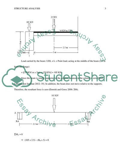
Structural Analysis Lecturer Structural Analysis Assumptions The analysis shall be done on the assumption that the column and beam are homogenous. In other words, it shall be assumed that the material density for the two elements, column and the beam, is uniform throughout the elements (Case and Ross 1999: 68). The analysis shall also be done on the assumption that the column is fixed to the ground, such that it will not overturn owing to the loading subjected to it. Specifically, it shall be assumed than the non-centric loading arising from the beam (applied to the flange of the column) shall not result to overturning the column. Instead, the overturning shall be overcome by ground reaction at the column base. a. Determining the Combined Stress Distribution at the Top of the Column Replacing n1 by 1 and n2 by 5, the column cross section is shown in figure 1 The beam, together with its loading and support, is shown in figure 1. Load carried by the beam: UDL x L + Point load, acting at the middle of the beam (2.5 m from the flange) = [(16 KN/ m x 5m) + (25 KN)] = 105 KN Since the beam is simply supported at the column, moment at the column is zero (Steel Construction Institute 2012: 35). In addition, the beam does not move relative to the supports. Therefore, the resultant force is zero (Emmitt and Gorse 2006: 206). ƩMA = 0 (105 x 2.5) – (RB x 5) = 0 5RB = 262.6 RB = 52.5 ------------------------------------------------------------------------------------- (1) ƩFy = 0 RA + RB = 105 ------------------------------------------------------------------------------- (2) Combining equation 1 and 2 gives: RA = 52.5 KN Therefore, the force acting along the flange of the column is equal to 52.5 KN. Similarly, the reaction at the flange, due to this force, is 52.5 KN. We now do away with the beam and consider the column. We consider only the load acting on the flange (from the beam) and the point load. At the top, the column experiences two types of stress: compressive stress, and tensile stress. The column is expected to experience maximum compressive stress on the flange carrying the beam while maximum tensile stress will be experienced on the flange opposite to the one carrying the beam. This is shown using the figure below, which shows the longitudinal section of the column and the loading. F represents the flange while w represents the web. Reactions at the flange and webs are shown. As shown in the figure, the column is eccentrically loaded. Moments at any point are zero since the column should resist bending. Further, resultant forces in the vertical direction should be zero since the column should be stable (Dabby and Bedi 2012: 112). Ʃfy = 0 RFA + RW + RFB = 285 KN + 52.5 KN RFA + RW + RFB = 337.5 KN---------------------------------------------- (3) ƩMW = 0 (52.5 x 0.1015) + 0.1015 RFA – 0.1015 RFB = 0 RFB – RFA = 52.5 KN RFB = 52. 5 - RFA ----------------------------------------------------------- (4) ƩMFB = 0 0.203 RFA + 0.1015 RW = 18.7775 KN--------------------------------------- (5) Substituting equation 4 to equation 3, RFA + RW + (52. 5 - RFA) = 337.5 KN RFA + RW + 52. 5 - RFA = 337.5 KN RW = 285 KN ------------------------------------------------------------------- (6) Substituting equation 6 to equation 5, we get that RFA = -50 KN (implying that the flange will be under tensile stress, which will be resisted by the material tensile strength). Considering equation 3, we get that RFB = 102 KN implying the flange nearest to the beam will be under compression. This is summarized in the figure below. Getting pressure distribution σ = F/A Where F = force acting at the point A = cross section Area σFA = -50/(0.181 x 0.009) = -30693 KPa At FA, the column will experience a tensile stress of 30.69 MPa σW = 285/ (0.015 x 0.185) = 102702 KPa At W (web), the column will experience a compressive stress of 102.7 MPa σFB = 102/ (0.181 x 0.009) = 62615 KPa At FB, the column will experience a compressive stress of 62.6 MPa. Therefore, maximum stress is experienced along the axis of the column while minimum stress is experienced at the flange opposite the beam. The second moment of inertia (I) for the column and the line of action for the force are then determined.    Eccentricity We know that σ Where y =  = 101.5 mm and x is the eccentricity Tensile edge: -30693 -30693 Therefore, eccentricity =6.068 mm from the centre of the column. Combined stress ƩMB = 0 (50 x 203) – (185 x 101.5) – (X x 95.432) = 0 10150 – 18777.5 – 95.432 X = 0 X = 90.4 kN X = 171.3 kN Therefore, combined load is 90400 N at an eccentricity of 6.068 mm as shown in the figure below. Bending moment Bending moment will be produced by the eccentrically applied combined load Bending moment = combined load x eccentricity = 90400 N x 6.068 mm Bending moment = 548547.2 Nmm Bending Stress Bending stress = My/I = 548547.2 Nmm x 101.5 mm/38591044.75 mm4 Bending Stress = 1.44 N/mm2 Direct stress = F/A = (90400/1629) Mpa Bending stress = 55.49 N/mm2 Combined Stress Diagram Combined Stress = Bending stress + Direct Stress Combined Stress = 56.93 N/mm2 Combined Stress Diagram b. Determining the Combined Stress Distribution at the base of the Column At the base of the column, as opposed to top, the column is subjected to additional loading arising from its weight, which acts along the axis of the column. Density = mass / volume Density = 7200 kg/m3 Volume = cross sectional are x height = [(0.181 x 0.009) + (0.181 x 0.009) + (0.015 x 0.185)] m2 x 6 m = 0.0362 m3 Mass = Density x Volume Mass = 7200 kg/m3 x 0.0362 m3 Mass of the column = 260 Kg Weight of the column 260 x 9.81 = 2556 N = 2.56 KN It shall be assumed that the column is resting on an even and uniform ground such that the ground supports the column by exerting reaction on every part of the column depending on the weight of the section (Gorenc et al. 2005: 382). Therefore, the column shall be divided into three components: flanges (2) and the web. The force due to weight of the components shall be added to the weight due to external loading (shown above). Flanges: load due to weight = (6 x 0.181 x 0.009) m3 x 7200 kg/m3 x 0.00981 KN/ kg = 0.69 KN Web: Load due to weight = (6 x 0.015 x 0.185) m3 x 7200 kg/m3 x 0.00981 KN/kg = 1.18 KN The loads will act as shown in the figure below, which combines all the loads (internal and external). Moments at any point are zero since the column should resist bending. Further, resultant forces in the vertical direction should be zero since the column should be stable. Ʃfy = 0 RFA + RW + RFB = 0.69 KN + 186.18 KN + 53.19 RFA + RW + RFB = 239.88 KN---------------------------------------------- (7) ƩMW = 0 (53.19 x 0.1015) + 0.1015 RFA – 0.1015 RFB + (0.69 x 0.1015) = 0 5.4 + 0.1015 RFA – 0.1015 RFB + 0.07 KN = 0 0.1015 RFA – 0.1015 RFB = -5.47 KN RFA – RFB = -53.89 KN ---------------------------------------------------- (8) ƩMFB = 0 0.203 RFA + 0.1015 RW – (0.69 x 0.203) – (186.18 x 0.1015) = 0 0.203 RFA + 0.1015 RW = 0.14 + 18.9 0.203 RFA + 0.1015 RW = 19.04 ----------------------------------- (9) Substituting equation 8 to equation 7, RFA + RW + (RFA + 53.89) = 337.5 KN RFA + RW + 52. 5 - RFA = 239.88 KN RW = 187.38 KN ------------------------------------------------------------------- (10) Substituting equation 10 to equation 9, we get that RFA = -0.10 KN. This implies that the flange will be under tensile stress, which will be resisted by the material tensile strength. However, the tensile stress will be less compared to the top of the column since the weight of the column acts to minimize it. Considering equation 7, we get that RFB = 52.6 KN implying the flange nearest to the beam will be under compression. This is summarized in the figure below. σFA = -0.1/(0.181 x 0.009) = -61.39 KPa At FA, the column will experience a tensile stress of 61.39 KPa σW = 187.38/ (0.015 x 0.185) = 67524 KPa At W (web), the column will experience a compressive stress of 67.5 MPa σFB = 52.6/ (0.181 x 0.009) = 32289 KPa At FB, the column will experience a compressive stress of 32.29 MPa. Therefore, maximum stress is experienced along the axis of the column while minimum stress is experienced at the flange opposite the beam. The second moment of inertia (I) for the column:    Eccentricity We know that σ Where y =  = 101.5 mm and x is the eccentricity Tensile edge: 61390 0.006139 Therefore, x = 2.334 mm Eccentricity = 2.334 mm from the centre of the column. Combined Load ƩMB = 0 (10 x 203) – (187.38 x 101.5) – (X x 99.166) = 0 2030 – 19019.07 – 99.166 X = 0 -99.166 X = 16989.07 X = 171.3 kN Therefore, combined load is 171.3 kN at an eccentricity of 2.334 mm as shown in the figure below. Bending moment will be produced by the eccentrically applied combined load Bending moment = combined load x eccentricity = 171300 N x 2.334 mm Bending moment = 399814.2 Nmm Bending stress = My/I = 399814.2 Nmm x 101.5 mm/38591044.75 mm4 Bending Stress = 1.05N/mm2 Direct stress = F/A = (171300/1629) N/mm2 Direct stress = 105.16 N/mm2 Combined Stress Combined stress = Direct stress + Bending stress = 105.16 + 1.05 = 106.21 N/mm2 Combined Stress = 106.21 N/mm2 Combined stress diagram Bibliography Case, J., Chilver, H., and Ross, C. 1999. Strength of Materials and Structures. Jordan Hill, Oxford: Butterworth-Heinemann, 68. Dabby, R., and Bedi, A. 2012. Structure for Architects: A Primer. Hoboken, NJ: John Wiley & Sons, Inc., 112. Emmitt, S., and Gorse, C. 2006. Barrys Advanced Construction of Buildings, Second Edition. United Kingdom: Wiley-Blackwell, 206. Gorenc, B., Tinyou, R., Gorenc, E., and Syam, A. 2005. Steel Designer’s Handbook, Seventh Edition. Sydney, Australia: University of New South Wales Press Ltd, 382. Steel Construction Institute (SCI) (Ed). 2012. Steel Designer’s Manual, Seventh Edition. West Sussex, UK: Blackwell Publishing, 35. Read More
Cite this document
  • APA
  • MLA
  • CHICAGO
(Advanced Construction of Buildings Report Example | Topics and Well Written Essays - 1500 words, n.d.)
Advanced Construction of Buildings Report Example | Topics and Well Written Essays - 1500 words. https://studentshare.org/engineering-and-construction/1770662-structure-analysis
(Advanced Construction of Buildings Report Example | Topics and Well Written Essays - 1500 Words)
Advanced Construction of Buildings Report Example | Topics and Well Written Essays - 1500 Words. https://studentshare.org/engineering-and-construction/1770662-structure-analysis.
“Advanced Construction of Buildings Report Example | Topics and Well Written Essays - 1500 Words”. https://studentshare.org/engineering-and-construction/1770662-structure-analysis.
  • Cited: 0 times

CHECK THESE SAMPLES OF Advanced Construction of Buildings

Architectural Features of Major Urban Monuments in Paris

It came into place after the demolition of an older building in order to come up with a complex of buildings which took the format of the rings of a private house.... At the end of the construction, it appeared to be a quadrangle that had a gateway centered at the downstream and also had paired pavilions....
6 Pages (1500 words) Essay

The Pyramids At Giza

The pyramids at Giza are still one of the most marvelous and mysterious buildings on the planet.... The Pyramids At GizaThe pyramids at Giza, which are often referred to as one of the Seven Wonders of the Ancient World, are still one of the most marvelous and mysterious buildings on the planet.... Thus, some researchers suggest that the pyramids were constructed by another more advanced civilization while the vast majority of scientists believe that these buildings are human-made....
2 Pages (500 words) Essay

Blurring the Boundary Between Real and Digital World

The paper "Blurring the Boundary Between Real and Digital World" says that the construction field has changed dramatically over time with the use of technology.... hellip; Virtual reality has put a new face on the business of construction making it light and easier for not only the clients and potential clients but also for the people working in the business.... It helps to cut down construction time and minimizes the wastage of resources.... It is the future of construction whether the change comes gradually....
6 Pages (1500 words) Essay

Description of the Conditions that Are Prerequisites to the Construction of the Cafeteria in Berlin

"Description of the Conditions that Are Prerequisites to the construction of the Cafeteria in Berlin" paper briefly describes the technological application during the technical architectural and building process.... It will describe the challenges that the construction process is likely to experience.... aving considered the issue of space and from the conceptual design of the cafeteria site, it is essential to consider building the construction into more than one story....
11 Pages (2750 words) Assignment
sponsored ads
We use cookies to create the best experience for you. Keep on browsing if you are OK with that, or find out how to manage cookies.
Contact Us