StudentShare
Contact Us
Sign In / Sign Up for FREE
Search
Go to advanced search...
Free

Civil Engineering Construction: A3 Hindhead Tunnel - Case Study Example

Cite this document
Summary
A case study outlines the structure and fabric of the A3 Hindhead tunnel. A paper has been presented based on the design, construction, and function based on the use of materials and economic limitations…
Download full paper File format: .doc, available for editing
GRAB THE BEST PAPER94.7% of users find it useful
Civil Engineering Construction: A3 Hindhead Tunnel
Read Text Preview

Extract of sample "Civil Engineering Construction: A3 Hindhead Tunnel"

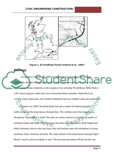
Civil Engineering Construction: A3 Hindhead Tunnel A3 Hindhead Tunnel Hindhead is a village on the main A3 trunk road. According to Godalming Cycle Campaign (2006) the A3 Hindhead project includes a 1.9 km tunnel located in Surrey, UK. More than 23000 vehicles pass though it each day. The Devil’s Punch Bowl and Gibbet Hill rises to approximately 270m, and is cut into two by A3 running along its western slope. The A3 is a single carriageway from London to Portsmouth. There are frequent holdups. After consideration of several bypass routes, the idea of a tunnel was considered. The cost of the scheme was £240m. Tough the routing of approach roads caused significant landscape and habitat damage, according to Whyte (2007) the A3 scheme has been estimated to have a major influence on the vitality of the local community and surrounding countryside. The tunnel is expected to open in 2011. More than 400 hectares of open access heath land will be freed from the current impact of A3. A part of the redundant A3 has been left open for non-motorised traffic not permitted in the tunnel. The areas will be easily accessible to users such as walkers, horse-riders, cyclists and people with disabilities. Figure 1. A3 Hindhead Tunnel (Ireland et al., 2007) Geology According to Ireland et al. (2007) the Hindhead area is made of fine grained sedimentary deposits laid down during the Lower Cretaceous period. This is near the shore transgressive marine conditions on the margins of the subsiding Weald Basin. Hythe Beds is a 90 m thick sequence within the Lower Greensland Series formation. Hythe Beds are variably sorted, glauconitic, and variably bioturbated and cross-bedded sands and sandstones. Ireland et al. (2007) described Hythe bed unit as made of 6 lithostratigraphic subdivisions, and the tunnel passes through them. The southern end of the tunnel passes through the Upper Hythe A and B. The units are similar and have an increasing number of sandstone bands with depth. They have been described as medium dense thinly bedded and thinly laminated, clean to silty and clayey fine and medium sand with subordinate to strong sandstone cherty sandstone and chert. The major portion of the tunnel passes through Upper Hythe C and D, and Lower Hythe A units. This has been described as Weak, locally very week to moderately strong, slightly clayey fine to medium sandstone with occasional thin beds of clayey/silty fine sand. The Lower Hythe B has been avoided and clays and sand become dominant in the lower half. The UCS values between 2 and 5 MPa for sandstone within Upper Hythe C/D. There are six joint sets including sub-horizontal bedding and the mean fracture centers vary between 190 and 815mm. The tunnel lies above the historically observed water table, and the maximum predicted water table exceeding the inert level in one location. Figure 2. Geological Profile (Ireland et al., 2007) According to Ireland et al. (2007) the ground model was defined for unusual material that had not been tunnelled previously. Determination of rock mass strength and stiffness was a challenge by the use of methods such as GSI, RMR or the Q-method. This was because strength and stiffness are determined from data from significantly stronger rocks. The sand-stone material ranged from weak to very weak, with upto 20 percent interbedded soil layers. Sandstone ranged 2-5MPa in strength, and the influence from soil layers were unaccounted leading to significant overestimation of stiffness. Sonic testing, pressuremeters and triaxial testing were used to determine the Elastic Modulus of the rock mass. Sonic testing over-estimated the stiffness, while triaxial resting under-estimated the stiffness. The most reliable method was pressuremeter testing. A small strain stiffness model was the interpreted model, where stiffness of the rock mass varied with strain. The Mohr-Coulomb strain softening model was used for strength. Also, the rock mass stiffness was related to depth for taking advantage of positive effects of larger insitu stresses. Road design considerations and environmental constraints influenced horizontal alignment of the tunnel. According to Ireland et al., (2007) this resulted in a reverse curve through the tunnel with a minimum radius of 1050m. Geological constraints influenced the vertical alignment. The aim was to minimize the length of the tunnel through the sand at the southern end for keeping the tunnel above the water table and maximize the vertical clearance to Lower Hythe B material. This was because the material had insufficient strength for carrying horizontal stress around the tunnel opening. The Devil’s Punch Bowl is a spring-shaped valley system re-entrant, where erosion fed backwards from the Hythe Bed/Atherfield Clay interface at the valley base. As the tunnel passed beneath the Devil’s Punch Bowl, the crossing of the punchbowl provided a clear constraint to the tunnel, and the coverage changed rapidly from minimum of 16m to maximum cover of 58m in a horizontal distance of 130m. Following the optimal tunnel material and avoiding the softer Lower Hythe B material resulted in a low point within the tunnel. Figure 3. Ground Model for Design (Ireland et al., 2007) The tunnel geometry has been illustrated in the figure below. The figure indicates longitudinal ventilation, drainage, and control and communication systems (Hall, 2003). According to the Highways Agency (2004) construction was originally planned for a period of over five years for the new road and tunnel. A period of six months has been estimated to carry out works on existing A3. Sequential excavation method tunnelling through weak sandstone using innovative methods has made the construction an interesting case study. Tunnel Excavation and Support Sand layers upto 2 m thick caused selection of sequential excavation methods and support techniques. Shotcrete is sprayed at the face of each excavation advance in the Sprayed Concrete Lining also known as the New Austrian Tunnelling Method. Ireland et al., (2007) found that as sand layers and low bond stress would negatively impact the effectiveness of rock reinforcement, the standard rock tunnel support techniques were not considered suitable. General excavation with full face heading with bench excavation followed at a distance. A closed invert was not required as the ground was stable and located above the water table. The horse shoe shaped primary lining was supported by elephants feet. Main support type has been adopted through the sandstone. Additional support measures such as spiling, face support wedges and/or face dowels have been adopted as a prevention against instability in excavation. Figure 4. Primary Lining through Rock (Ireland et al., 2007) Figure 5. Primary Lining through Sand (Ireland et al., 2007) Primary lining through rock and sand have been illustrated in the figure. According to Ireland et al., (2007) primary lining was designed as permanent. Non-alkaline accelerators with no loss in shotcrete strength were used. Spilling was in several locations as a consequence of adverse soil layers. Self-drilling Glass Reinforced Plastic dowels with no adverse durability issues were used. Sprayed concrete was reinforced with steel fibres for safe installation. The curved shape of the section allowed moments resisted by axial forces within the lining. Secondary Lining Ireland et al., (2007) described the secondary lining is designed to support the proposed sheet waterproof membrane and provide fire resistance to the tunnel. Plain concrete is used to construct the secondary lining from plain concrete with tensile loads in the lining resisted by tensile capacity of the concrete. This allows minimization of heat of hydration and shrinkage. 35 percent pulverized fly ash cement replacement mix design with low shrinkage. Addition of 1-2 kg/m3 of polypropylene fibers are added to the concrete mix for preventing explosive spalling. Fire testing was used to determine the precise dosage. Construction The Highways Agency is managing the project for the Secretary of State. Balfour Beatty is the contractor and Mott MacDonald is the designer. The contract was awarded in 2002. Sprayed Concrete Lining technique is being used for construction. Heading and bench are two stages of excavation. According to Arnold (2009) the advancement is one and two metres at one time based on ground conditions. This is followed by spraying of 200 mm thick lining. At the north portal construction activity is 24/7 along the Hythe beds, where the there is silted weak sandstone or weakly cemented sand. Construction along the south portal is on a 6 day shift where the ground is weaker. 12m long canopy tubes support the crown. The installation is such that a 4 m overlap is achieved with the previous set. When ground conditions are good, progress of 110 metres can be achieved. Figure 6. Twin Tube Bore Tunnel (Arnold, 2009) Figure 7. Tunnel Construction (Arnold, 2009) Figure 8. Tunnel Design (Hall, 2007) Figure 9. Design and Fit (Hall, 2007) Cross Section There are twin 2-Lane bores that cross passages at 100m nominal centers. Two 3.65m lanes make up the bores. The bores are made of full batter cups and 1.2m wide verges on each side of the tunnel. Verges allow sight-lines for the horizontal curvature for accommodating electrical services and provision of wheelchair access for crossing passages and emergency points at 100m nominal centers along the tunnel. Vertical traffic gauge is 5.03m with additional clearance of 250mm to the Equipment Gauge. The drainage system is continuous, and located beneath the curb and verge with cable duct bank. Services such as fire main, high voltage cables and pump mains are buried beneath the carriageway. The lighting and communication cables and jet fans are contained within the crown. The resulting tunnel structure is horseshoe shaped with an internal diameter of 10.6m and excavated diameter of 11.6m (Ireland et al., 2007). Figure 10. Cross Section (Ireland et al., 2007) Innovation According to Arnold (2009) the design allowed for safety in construction and operation during maintenance and unplanned incidents. There are two bores, and cross passages at every 100 m connect the bores for emergency evacuation. There are multi phase lighting, ventilation fans, communication cables that are ducted, roadside telephones, hydrants and drainage. The services can be operated manually or by the use of remote control. The Services Building has 24/7 access with equipment available. There is a dedicated safe access road in addition to the main line. This allows safe access for emergency vehicles for marshalling of plant and safety equipment before planned maintenance closures. Materials have been selected for minimization of unplanned maintenance interventions. Materials have been selected for long lives or easy renewal. The alignment of the tunnel is above the water table for reduction of drainage requirements, and longer duration of materials. The initial sprayed concrete lining has been designed for structural strength. The secondary lining has been designed for water proofing, fire resistance and finish. The need for reinforcement in the secondary lining has reduced cost, besides deterioration from corrosion. Electrical cabinets have been located in tunnel cross-passages allowing access to control cabinets from either bore. This has enabled planned maintenance closures easier, and reduced the ingress protection rating required to protect the equipment. Crossing points have been provided in the central reserve at the portals to enable switching of traffic for running in contra-flow in a single bore during emergencies or scheduled maintenance activities. Fire and Life Safety Provisions According to Ireland et al., (2007) safety provisions include cross passages at 100m nominal centers for escaping to non-incident bore. Fire hydrants, dry pipe connections, fire extinguishers and emergency telephones have been included in the cross passages. There are Emergency Points at 100m nominal centers located at mid-point between cross passages. There are emergency telephones and fire extinguisher in each EP. There are 20 jet fans per bore for smoke control within a longitudinal ventilation system. Cost benefit grounds did not allow inclusion of fire suppression system. However, space provision was made for the future installation of fire suppression system. Salient Features Arnold (2009) described the salient features of the project. It is one of the first and Early Contractor Involvement Schemes; has deployed key supply chain partners early resulting in innovation and safety through good design; engaged early with stakeholders for optimizing the operational safety; carried out risk assessment systematically evaluating impacts on operational safety; achieved savings of £10M in costs through systematic innovation; and produced innovative design for safety and efficiency. Ireland et al. (2007) described the benefits of using TBM were that it eliminated the vertical alignment for following the optimal material for ground support. As a result the tunnel could fall from south to north allowing the deletion of low-point sump. The primary disadvantage was that TBM options were openings required at emergency points and cross passage junctions. The junctions are very expensive for a TBM tunnel. When benefit cost ratio for emergency points was greater than 1 for SCL tunnel, the cost for opening TBM tunnel resulted in BCR < 1. The benefit for TBM option was minimal because SCM tunnel was proposed concurrently from 4 faces. The TBM had to excavate one bore and then be turned for excavation of the second bore. The total bore length was 3.6 km which was insufficient to give TBM a significant program advantage. A length of 2.5 km would have been required for a significant advantage for the TBM. The TBM option had a lead time for procurement of 12.0m diameter machine. Figure 11. TBM Tunnel Cross Section (Ireland et al., 2007) According to Ireland et al. (2007) there was a focus on minimization of whole life costs and development of corresponding design influenced by life cycle costs of managing tunnel assets and health and safety regulations. Design for maintenance includes minimization of unplanned maintenance interventions; consideration of safety of maintenance included deletion of equipment wherever possible, selection of materials with for longest design life possible, provision of safe maintenance access, and provision of replacement options for infrastructure; maintenance of risk assessments including specific design initiatives; provision of spare HV conduit and blind pits for allowing replacement of HV cables in routine closures; modular hydrant connections for replacement in routine closures without disturbance of cable ducts and other services; and relocation of in-tunnel sump to outside tunnel. A directional drilled gravity drain allowed maintenance access to sump without tunnel closure. Conclusion The Hindhead area is comprised of fine grained sedimentary deposits. A ground model was defined for unusual material that had not been tunnelled previously. Sequential excavation method tunnelling through weak sandstone using innovative methods has been used for construction of the A3 Hind Tunnel. Sprayed Concrete Lining technique is being used for construction. Salient features include early involvement of contractor; efficient supply chain management; management of risk and operational safety; and innovation in design. References Arnold, P. (2009). A3 Hindead tunnel construction. Available: http://www.innovationandresearchfocus.org.uk/articles/pdf/issue_76/issue_76.pdf. Last Accessed 24 April 2010. Godalming Cycle Campaign. (2005).A3 Hindhead: Playing the Second Fiddle. Available: http://www.godalmingcycle.org.uk/conference/Hindhead%20script.pdf. Last Accessed 24 April 2010. Hall, R. (2007). UK case study: A3 Hindhead Tunnel. Available: http://publications.piarc.org/ressources/documents/actes-seminaires07/C33-france0207/6-DG-QRAM-UK-case-study.pdf. Last Accessed 24 April 2010. Highways Agency. (2004). A3 Hindhead Scheme. Available: http://www.highways.gov.uk/roads/documents/61_nts_may2004.pdf. Last Accessed 24 April 2010. Ireland, T., Rock, T. & Hoyland, P. (2007). Planning and Design of the A3 Hindhead tunnel, Surrey, UK. Underground Space. Taylor & Francis. London. 1001-1007. Whyte. I. (2007). A3 Hindhead major improvement works newsletter 8. http://www.highways.gov.uk/roads/documents/S070011_A3_Hindhead_Newsletter_8_Web_Version.pdf Read More
Cite this document
  • APA
  • MLA
  • CHICAGO
(Civil Engineering Construction: A3 Hindhead Tunnel Case Study, n.d.)
Civil Engineering Construction: A3 Hindhead Tunnel Case Study. Retrieved from https://studentshare.org/engineering-and-construction/1736979-tunnels
(Civil Engineering Construction: A3 Hindhead Tunnel Case Study)
Civil Engineering Construction: A3 Hindhead Tunnel Case Study. https://studentshare.org/engineering-and-construction/1736979-tunnels.
“Civil Engineering Construction: A3 Hindhead Tunnel Case Study”, n.d. https://studentshare.org/engineering-and-construction/1736979-tunnels.
  • Cited: 0 times

CHECK THESE SAMPLES OF Civil Engineering Construction: A3 Hindhead Tunnel

The Strait of Messina Bridge Project

civil engineering Project civil engineering projects involve constructing and renovating a structure or alteration done in the environment.... A civil engineering project may involve beginning a non-existed project to meet a requirement of to solve a certain issue.... The management of a civil engineering project involves a high level of documentation.... The different ways were, one the suspension bridge, second the floating tunnel and finally the bored tunnel....
6 Pages (1500 words) Essay

The Channel Tunnel Project and the Way in Which It Was Planned and Expected To Be Carried Out

This research is being carried out to evaluate and present the Channel tunnel project, focusing on the way in which it was planned and executed.... nbsp; Following the analysis and critique of the project, the final section of the report gives recommendations as to how to improve the process....
12 Pages (3000 words) Essay

Risks Management Analysis of the Channel Tunnel Project

Name: Course: Date: Risks management analysis during Construction stage and Operational stage of the Channel tunnel Project Construction Phase The construction phase falls in the implementation stage of the Channel tunnel Project.... hellip; Resources management is a fundamental aspect of the construction phase of the Channel tunnel Project, which ensures that the resources are applied objectively towards their intended purposes, without any mixing of the resources of the different project activities (Lycett, 2004 p294)....
3 Pages (750 words) Term Paper

Why engineering at FSU

Its avowed mission is to engender quality, growth and diversity and there are some 200 odd companies and government organizations that… civil engineering is deeply involved with community service, development and improvement planning, design, construction, operation and maintenance of the facilities that are indispensable for contemporary life.... civil engineering is deeply involved with community service, development and improvement planning, design, construction, operation and maintenance of the facilities that are indispensable for contemporary life....
2 Pages (500 words) Essay

Use of NRA and CESMM3 Methods in Civil Engineering Measurement

The formworks also vary on plane, curves, voids, and constant cross-section concrete (CESSM3, 1991 It is not measured to construction joints, holes, ducts, sockets, mortices and the like that do not exceed 0.... Various thicknesses are indicated in the placing of concrete.... For blinding, a thickness of not greater than 150mm is allowed....
7 Pages (1750 words) Assignment

The Specialization and Concentration of Civil Engineering

civil engineering involves the engineering of construction and forms a significant component of the building and construction field (Brown University, 1).... These require that students take appropriate concentrations or specialization in civil engineering so as to 4 February Specialization/Concentration of civil engineering civil engineering involves the engineering of construction and forms a significant component of the building and construction field (Brown University, 1)....
1 Pages (250 words) Essay

( the module name : underground construction)

According to the analysis, hock-brown criterion was used to… The parameter provides a good analysis for the design of the tunnel since it is on a hard rock.... According to the analysis, hock-brown criterion was used to determine the failure at the tunnel side-line.... The parameter provides a good analysis for the design of the tunnel since it is on a hard rock.... )One of the most suitable tunnel construction techniques is the Mechanized Tunneling- the TBM....
1 Pages (250 words) Essay

The Drag Features of the Wind Tunnel

Moreover, it assesses the Reynolds numbers coupled with certification of the model prototype criterion. The prevailing tunnels employed in the determination… Moreover, the tunnel entails the effuser, contraction section, operating section coupled with the diffuser and fan. The drag is the force of the body resulting from the fluid that resists motion within the direction of Moreover, the drag ought to oppose force within the opposite direction in order maintain or escalates the velocity of the object....
3 Pages (750 words) Essay
sponsored ads
We use cookies to create the best experience for you. Keep on browsing if you are OK with that, or find out how to manage cookies.
Contact Us