StudentShare
Contact Us
Sign In / Sign Up for FREE
Search
Go to advanced search...
Free

Modeling the Bracket in Solidworks - Assignment Example

Cite this document
Summary
This assignment "Modeling the Bracket in Solidworks" focuses on modeling a bracket using Solidworks and then measuring the amount of displacement and stress using Finite element analysis. From the results in the first part, the bracket was to be re-modeled…
Download full paper File format: .doc, available for editing
GRAB THE BEST PAPER95.1% of users find it useful
Modeling the Bracket in Solidworks
Read Text Preview

Extract of sample "Modeling the Bracket in Solidworks"

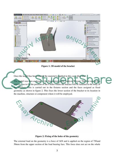
Number: EAT216 Summary The aim of this assignment was to model a bracket using Solidworks then measure the amount of displacement and stress using Finite element analysis. From the results in the first part, the bracket was to be re modelled using recalibrated dimensions in order to achieve maximum work output when it is put to actual task in a real life application Introduction The entire design process is meant to maximize the potential of the bracket performance through the following ways: By carrying out marginal shape deviation of the model while maintaining the strength and deflection in the desired measure. By reducing the weight of the bracket. The initial procedure is to model the bracket in Solidworks according to the dimensions as per the instructions. Thereafter, Finite element analysis was done to determine the stress and displacement of the bracket. The results are then used to undertake weight optimisation of the model. The limits of the redesigned model are the face bearing the load, strength of the load and the fixed points which are not alterable. The only changing variables are the geometry and materials used. Part A The bracket was modelled from the drawing given and figures 1 shows the 3D model of the bracket. Figure 1: 3D model of the bracket Once the model has been created the material is applied in this case alloy steel. The model was then analysed in the SimulationXpress Analysis Wizard. The first step in this process was to fix the position of the 4 holes where the bracket will be fastened to the body of the structure. This is carried out in the fixtures section and the faces assigned as fixed geometry as shown in figure 2. This fixes the lower section of the bracket to its location in the machine, structure or component where it will be employed. Figure 2: Fixing of the holes of the geometry The external load on the geometry is a force of 1kN and is applied on the region of 750and 50mm from the upper section of the load bearing face. This force does not act on the whole region hence a sketch is created 50mm from the upper section and creating a split line to allow the force to applied on the hatched region of the load bearing face on the drawing. Figure 3 shows the model with the split line created. Figure 3: Model showing the split line separating the load bearing region The force is then applied and the part is subjected to static analysis using the Finite Element analysis method. This is as shown in figure 4 below. Figure 4: The part with all the fixture and loads applied The part was meshed using the default settings in Solidworks and the analysis carried out by running the simulation. The simulation results are produced giving the stress, displacement, deformation and the safety factor. Determining the maximum displacement and stress is the key objective at this point. The maximum Von Misses stress is 737.96mPa while the yield stress is 620.422mPa. This shows that the stress experienced is higher than the yield stress and hence failure due to the 1KN load applied. This is shown in figure 5. Figure 5: Von Misses stress contours The maximum displacement is shown in figure 6. The displacement experienced is maximum at the upper edge of the load bearing region and the value is 0.9134mm. Figure 6: Displacement contours of the part Part B The results from part A are used to carry out a redesign of the bracket which are then validated with Finite Element Analysis. The main objective of this redesign work is to reduce the weight of the bracket by at least 10% and the deflection should not be more than 10%. The bracket was optimised by analysis of the regions which are highly stressed basing the enhancement on the boundaries of the redesign work. The constraints in this case were: 1. All fixing points of the bucket must remain the same in terms of size and position. 2. The load bearing face must undergo no modification in terms of size and position. 3. The load must be the same in terms of size and direction. The fixing points are the holes for fastening the bracket to the component it is attached. The four holes were retained in the redesign. In this redesign work, the material was the main focus for reducing the weight of the bracket. The aim was to select a material similar to steel but is lighter in weight. Aluminium alloys offered the best choice with Aluminium 2014-T6 taken as the best choice (ASHBY, M. F. 2005). The challenge is the strength and this was solved by adjusting the geometry of the stiffening web in the side opposite to the load bearing region and increasing the number. The mass of the initial bracket from the mass properties section is 94.89 grams. The redesigned model is as shown in figure 8. The mass of the model is 85.4 grams. Figure 7: 3D model of the redesign The reduction in weight= The initial bracket shows the maximum stress exceeds the yield stress when the 1kN force is applied. The redesign needs the yield stress to be higher than the maximum stress. The Aluminium 2014-T6 alloy is less strong than alloy steel hence the web supporting the structure is increased in size and the number increased to two. This increases the stiffness of the load bearing region and hence the displacement and the Von misses stress is reduced. The holes for fastening on the component were also fixed as in the previous model and the load of 1kN applied as shown in figure 9. Figure 8: The model with fixture and load applied The maximum Von misses stress is 486mPa and the yield strength is 415mPa. The difference is quite less than for the initial bracket. Figure 10 shows the Von Misses stress contours obtained in the FEA analysis. Figure 9: Von Misses stress contours of the redesigned bracket The displacement contour is as shown in figure 11 and the maximum deflection due the applied force is 0.4091mm. The reduction in the deflection after the redesign is given by Percentage reduction in displacement ==55%. The percentage reduction in deflection is beyond the expectation since aluminium is less strong. Figure 10: Displacement contours of the re-designed bracket Conclusion The analysis of the initial bracket and re-designed one was successful and the objectives set out at the beginning were met. The maximum deflection of the re-designed bracket reduces as compared to that of the original. The material was changed from alloy steel to Aluminium 2014-T6 and hence the weight of the bracket reduces by 10% after the re-design without significant effect on the performance. The maximum stress reduces from 620.422mPa to 486mPa. The design changes made in the bracket during the re-design process are made in this report. References ASHBY, M. F. (2005). Materials selection in mechanical design. Amsterdam, Butterworth-Heinemann. http://www.books24x7.com/marc.asp?bookid=25372. Read More
Cite this document
  • APA
  • MLA
  • CHICAGO
(“FEA Assignment Example | Topics and Well Written Essays - 1750 words”, n.d.)
FEA Assignment Example | Topics and Well Written Essays - 1750 words. Retrieved from https://studentshare.org/engineering-and-construction/1690118-fea
(FEA Assignment Example | Topics and Well Written Essays - 1750 Words)
FEA Assignment Example | Topics and Well Written Essays - 1750 Words. https://studentshare.org/engineering-and-construction/1690118-fea.
“FEA Assignment Example | Topics and Well Written Essays - 1750 Words”, n.d. https://studentshare.org/engineering-and-construction/1690118-fea.
  • Cited: 0 times

CHECK THESE SAMPLES OF Modeling the Bracket in Solidworks

Tax Brackets and Deductions

In the United States, income tax is imposed by the federal government, states or local authorities.... Income tax is obtained by applying tax rates applicable for the current financial period.... Individuals and.... ... ... Taxpayers are expected to review their income tax by filing tax returns from which relevant deductions can be made to obtain the actual amount owed in taxes by the taxpayers....
1 Pages (250 words) Essay

Business Process Modeling Approaches

ost businesses carry out complex and very expensive business modeling approaches to improve their business.... Although these processes are beneficial in the end, they take long and their benefits BUSINESS PROCESS MODELLING APPROACHES Business process modeling refers to the process of analyzing and improving the current business processes of a business.... Most businesses carry out complex and very expensive business modeling approaches to improve their business....
2 Pages (500 words) Article

SolidWorks CFD

CFD was the method of choice in the past decade in the design of most automotive, aerospace, and industrial processes and components in which There are several commercial CFD packages accessible for modeling flow in or around objects in the fluid dynamics.... Hence, the proper modeling of transition, including both the onset and the extent of the transition will lead to more accurate drag prediction....
5 Pages (1250 words) Assignment

AutoCAD and Solidworks

The major part of the motor base was the bracket which was properly dimensioned.... "AutoCAD and solidworks" paper exposes a wide range of skill sets and concepts that we used to represent accurately the drawings provided in different drawing platforms i.... AutoCAD and solidworks.... Getting the correct profile of the lower part using solidworks was difficult as the software provides for modifications on the end sketches only....
4 Pages (1000 words) Essay

Commercial Software Packages and Computer Assisted Design

Some of the 3D programs are Autodesk inventor, solidworks, CoCreate Solid Designer, VX CAD, Unigraphcs NX and Pro/Engineer SolidEdge.... Following is the example of this generic type:Figure 4: Example of Wireframe and Surface modeling Solid modeling It is useful in the calculation of the object's dimensions....
8 Pages (2000 words) Assignment

Application of Computer Aided Design in Mechanical Engineering

.... ... ... IntroductionComputer Aided Design (CAD) is designing using the information technology.... Any CAD system consists of specialized software and hardware.... It allows the designer and user to accurately generate graphic representation of a real life product.... IntroductionComputer Aided Design (CAD) is designing using the information technology....
4 Pages (1000 words) Assignment

Solidworks to Construct 3d Model of an Engineering Assembly

DesignThis is the geometric modeling like 2-D, and 3-D modeling, including drafting, part creation, creation of drawings with various views of the part, assemblies among others parts (Zegdoun et al.... .... ... ... 1.... IntroductionComputer Aided design (CAD) can be defined as one of the computer aided programs used in creating two or three dimension graphical representation of the physical object....
9 Pages (2250 words) Assignment

SolidWorks API Programming

The aim of the paper "SolidWorks API Programming" is to provide details on how API PROGRAM in solidworks was done to design a 10mm metal bolt.... ensure that the bolt is designed in solidworks then various conditions have to be made this include ... he bolt will have a head of a polygon in nature and an option of Polygon in solidworks will be considered ... API will be used to integrate various programs with the solidworks CAD package....
2 Pages (500 words) Assignment
sponsored ads
We use cookies to create the best experience for you. Keep on browsing if you are OK with that, or find out how to manage cookies.
Contact Us