StudentShare
Contact Us
Sign In / Sign Up for FREE
Search
Go to advanced search...
Free

Motor Speed Control - Essay Example

Cite this document
Summary
This essay "Motor Speed Control" focuses on three experiments: the Stepper Motor and Controller, the DC motor speed control, and the AC synchronous motor control. Further, each experiment that will be discussed involves two specific practical exercises. …
Download full paper File format: .doc, available for editing
GRAB THE BEST PAPER91.1% of users find it useful
Motor Speed Control
Read Text Preview

Extract of sample "Motor Speed Control"

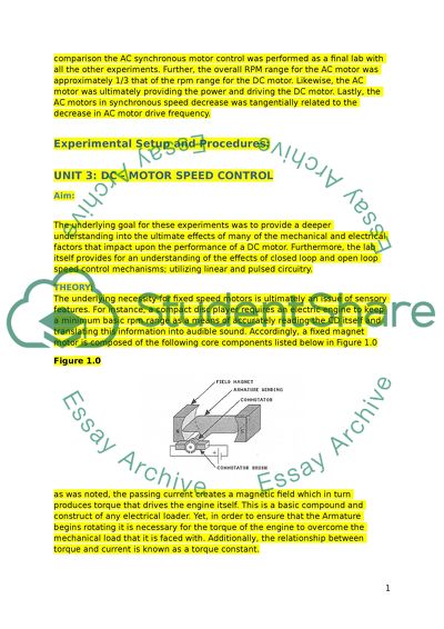
Contents Experimental Setup and Procedures UNIT 3: DC - MOTOR SPEED CONTROL Aim THEORY Exercise Analog Speed Control of a Dc motor 3 Results and Discussion: 3 Conclusion 3 Exercise 2 – Pulsed Speed Control of a Dc motor 3 Results and Discussion: 3 Conclusion 4 UNIT 4: AC SYNCHRONOUS MOTOR CONTROL 4 Introduction: 4 Theory: 4 CONCLUSION 5 EXERCISE 2: THE TACHOMETER GENERATOR 5 Introduction: 5 Results and Discussion: 5 CONCLUSION: 6 Introduction: For purposes of this discussion, three experiments will be related. These are as follows: the Stepper Motor and Controller, the DC motor speed control and the AC synchronous motor control. Further, each experiment that will be discussed involves two specific exercises. For instance, the DC motor speed control involved armature winding and commentator brush experiments. Additionally, the DC motor experiment received several unique approaches which involved a shunt wound, compound wound, and series wound. By means of contrast in comparison the AC synchronous motor control was performed as a final lab with all the other experiments. Further, the overall RPM range for the AC motor was approximately 1/3 that of the rpm range for the DC motor. Likewise, the AC motor was ultimately providing the power and driving the DC motor. Lastly, the AC motors in synchronous speed decrease was tangentially related to the decrease in AC motor drive frequency. Experimental Setup and Procedures: UNIT 3: DC - MOTOR SPEED CONTROL Aim: The underlying goal for these experiments was to provide a deeper understanding into the ultimate effects of many of the mechanical and electrical factors that impact upon the performance of a DC motor. Furthermore, the lab itself provides for an understanding of the effects of closed loop and open loop speed control mechanisms; utilizing linear and pulsed circuitry. THEORY: The underlying necessity for fixed speed motors is ultimately an issue of sensory features. For instance, a compact disc player requires an electric engine to keep a minimum basic rpm range as a means of accurately reading the CD itself and translating this information into audible sound. Accordingly, a fixed magnet motor is composed of the following core components listed below in Figure 1.0 Figure 1.0 as was noted, the passing current creates a magnetic field which in turn produces torque that drives the engine itself. This is a basic compound and construct of any electrical loader. Yet, in order to ensure that the Armature begins rotating it is necessary for the torque of the engine to overcome the mechanical load that it is faced with. Additionally, the relationship between torque and current is known as a torque constant. As the armature begins to rotate, it circumvents the magnetic field of the magnets. Accordingly, and electromotive force is required and generated in order to supply the voltage that is necessary to engage this particular operation. Lastly, it must also be understood that winding and the action of the commentator brushes requires its own level of resistance as well. Kt = torque Constance Ks= speed constant Cemf = Counter electromotive force Rt= terminal resistance PW/T = Duty factor Va= voltage applied T= torque Exercise 1 – Analog Speed Control of a Dc motor The exercise attempted to represent this illustration between the armature voltage and the overall speed at which the engine turns. Additionally, it illustrates a comparison between a closed loop system and an open loop circuit. Results and Discussion: The overall frequency of the AC motor output was determined to stand at 500 RPM rpmf500 = or 100 Hz. The constant for speed in the TACH circuit is described as follows: Ts = 58.1 rpm/V. The TACH circuit output voltage when the analog speed control = -7.0 Vdc is VTO = -7 Vdc. The motor’s current IA = -0.03 A. Therefore, the motor’s overall total torque equates to T = -1.65 mNm. The driver output (VA) voltage required to run the dc motor at -1220 rpm with a -0.6 mNm load.VA = -8.37 Vdc. Voltage at the driver output (VA = - 7.02 Vdc). The tach out voltage when the torque load = -3.3 mNm VTO = -7 Vdc. Conclusion It was concluded that it was necessary to set the motor speed to a specific pork level as a means of ensuring that the open loop control maintained a fixed voltage. By considering the cemf and the resulting la*RT, the research was able to obtain the necessary and required level of voltage for the mechanical load in question. By measuring the motor speed with a tachometer, these specific levels were able to be controlled and understood. Moreover, tachometer output exhibited a reverse relationship with the speed of the engine. Exercise 2 – Pulsed Speed Control of a Dc motor The underlying goals of exercise two can be summarized as follows: seeking to demonstrate the ability of power saving while utilizing a pulse mode control mechanism, a comparison of basic operations of analogue and pulsed mode operation for control closed circuit loops, and a demonstration of the operation capacity of a pulsed mode speed control circuit. In representing how the pulse mode control mechanism operated to save power, the experiment was able to provide the researchers with an understanding of the direction of motor efficiency; thereby providing analog speed signal. It was noted that the speed of the motor at a maximum rate could only be affected once the ac and dc motors were connected in tandem. Therefore, DVM was used to measure the driver output voltage with regard to GND. After this was achieved, analogue speed then varied between -10 Vdc +- 0.2Vdc as the driver output (VA) and results are recorded. Subsequently, the duty load, factors of the driver output, as well as effective dc voltage (Va) levels were calculated. The final measurement that was engaged was necessarily an interpretation of the tachometer results. Results and Discussion: Once the parch was removed and the leads and two post connecters were mounted to the circuit board, the motor speed control was then set to CCW. DVM was measured by the driver output voltage with regard to GND; while adjusting the analog speed control for -9 Vdc +- 0.2Vdc at the driver output (VA). USING A DVM determines the dc motor average current. Ia=-9mA. The power amplifier had a -15 Vdc source (Vs). Likewise, the motor was supplied with -9Vdc at -9 mA. Calculating the amplifier output transistors dissipation power was determined by the following: Pt=54mW. Using the DVM to measure the tech out corresponded to a value of-8.36Vdc. Moving the two-post connectors at analog speeds to PWM speeds and adjusting the triangle control for mid position, the PWM speed control increased to an average of -9Vdc+_0.2Vdc at the driver output. Determining the dc motor’s average current equated to Ia=-9mA. Using an oscilloscope to help measure the amplitude of the driver output pulse revealed that this was represented as: Vpulse=-13.4Vdc. Calculating the output transistor’s power dissipation pulse yielded a value of Pt=-14.4mW. Using a scope to determine the duty factor at the driver output, we calculated that the effective dc voltage (Va) driving the motor was Pulse Va=-8.93Vdc. Measuring the tach noted a value of -8.1 Vdc. Conclusion The amplification is consuming the power delivered to the motor. Driving a DC motor with pulses is the same as using the regular DC voltage. UNIT 4: AC SYNCHRONOUS MOTOR CONTROL Introduction: To describe the electrical and mechanical factors that affect AC motors and generators. To achieve this, demonstration of speed control of a two-phase synchronous motor with the use of AC motor as generator will be employed. Theory: Figure 3 a: AC synchronous motor with a permanent rotor magnet The AC synchronous motor could only produce torque as the rotor speed was equal to the change in the stator’s magnetic field. The time required to accelerate the rotor was determined by the rotor and overall torque. The motor’s synchronous speed was calculated using frequency an AC (f) and number of stator poles (p). Equating to an rpm value = 120f/p Ultimately, there are two types of AC synchronous motors: single phase and two phase Figure 3b illustrates a two phase AC synchronous motor CONCLUSION Separate power amplifiers drove the AC motor stator coils A belt mechanically connected the two motors Each revolution of the AC motor pulley drove the DC motor pulley three complete revolutions The DC motor’s armature spuns between its field magnets; thereby creating emf. The DC motor’s output voltage (Vdcm) and its speed constant (Ks) wereused to calculate the DC-motor rpm (rpmdc). Rpmdc = 173 x Vdcm EXERCISE 2: THE TACHOMETER GENERATOR Introduction: Aims: To demonstrate the two phase AC generator operations To demonstrate the lpeak detector operation To utilize the AC generator and peak detector to measure RPM Results and Discussion: Firstly, we installed two post connects; one at the DC motor and the other that worked to match analog speed. Secondly, we set all speed controls to full CCW. Next, we used the DMM to determine the overall resistance of the phase 2 stator winding to be Rt2. Rt2=200ohm, Rt1=190ohm. The AC motor had two stator windings that appeared to be almost entirely identical. Both windings were positioned around one permanent magnet rotor. Rotating these generator rotors moved the MFLs across their own stator windings; producing voltage at every point that they connected. Adjusting for analog speed control, we then connected CH1 to the AC motor and then CH2 to the same motor. Adjusting for the overall display of several cycles to form two wavelengths, the sine waves of 90 degrees were determined to exist. When we measured the peak output voltage from Phase 1 (CH1), we determined that the generator was operating at 50rpm or Vgt=9Vpk. The generator’s speed constant was also recorded at K=55.5rpm/Vpk, where the generator’s rpm=249.7. CONCLUSION: When a conductor crosses a magnetic flux line, voltage is induced. The force required is proportional to the current induced Ac generators allow for polarity of output voltage to change. This occurs as the rotation reverses the magnetic field that previously existed The Number of flux lines that are present and cross a conductor during each revolution is determined by overall magnetic field strength as well as coil construction Ks = rpm/Vg Kt = T/Ig F = (rpm x P)/120 Read More
Cite this document
  • APA
  • MLA
  • CHICAGO
(“Lab report Essay Example | Topics and Well Written Essays - 1500 words - 2”, n.d.)
Lab report Essay Example | Topics and Well Written Essays - 1500 words - 2. Retrieved from https://studentshare.org/engineering-and-construction/1639070-lab-report
(Lab Report Essay Example | Topics and Well Written Essays - 1500 Words - 2)
Lab Report Essay Example | Topics and Well Written Essays - 1500 Words - 2. https://studentshare.org/engineering-and-construction/1639070-lab-report.
“Lab Report Essay Example | Topics and Well Written Essays - 1500 Words - 2”, n.d. https://studentshare.org/engineering-and-construction/1639070-lab-report.
  • Cited: 0 times

CHECK THESE SAMPLES OF Motor Speed Control

Electric Motors and Accuracy of Instrumentation System

(b) (i) Applications of Motors DC motor: It is much easier to control speed in case of DC motors and therefore, these motors are preferred for applications where speed control is very important.... AC motor: It is inexpensive; however, the speed control is not good.... One typical application of an AC motor is to drive fans where speed control is not so critical.... Servo Motor: It is feedback controlled system and hence it is used for applications which need precise position and speed control....
4 Pages (1000 words) Essay

Speed Control of DC and AC Machines

"speed control of DC and AC Machines" paper examines speed control of separately excited DC motor by armature voltage variation, operation of a single-phase half-controlled bridge rectifier, load test on separately excited DC motor, and the principle of speed control of a three-phase induction motor.... The use of feedback to obtain speed control of a motor is not a necessity in the case of using the rectifier to feed the armature winding....
14 Pages (3500 words) Lab Report

Design of Motor Speed Sampling, Amplification, Filtering and Display

he distinctive design of the electronic circuits for the control of Motor Speed Control and the subsequent display is the physical approach used in the creation of physical circuits that also check the variations in behavior of various electronic components with close reference to their working.... Primarily, this paper is tasked with the creation and extensive demonstration of the various electronic circuits that control the DC motor.... Additionally, there are a number of ways that the remote control can be used....
4 Pages (1000 words) Essay

Speed Control of a DC and AC Motor Machine

The author of the "speed control of a DC and AC Motor Machine" paper examines speed control of separately excited DC motor by armature voltage variation, operation of a single-phase half controlled bridge rectifier, and waveform of the motor armature voltage operation.... Achieving speed control is via the armature windings.... The use of feedback to obtain speed control of a motor is not a necessity in the case of using the rectifier to feed the armature winding....
11 Pages (2750 words) Lab Report

Speed Control of DC and AC Machines

rmature winding drives the motor and as a result of varying resistance and voltage properties of the armature will enhance the realization of Motor Speed Control.... The paper "speed control of DC and AC Machines" highlights that AC machines are able to vary the speed with time increase.... Rectifiers remove the need of having feedback for the purpose of obtaining speed control via changing the voltages fed to the armature winding of the motor....
11 Pages (2750 words) Lab Report

DC Motor Positioning

The "DC Motor Positioning" paper shows DC Motor Speed Control and AC synchronous motor control that power can bed efficiently by ac motor as compared to Dc motor.... The other objective will be to provide a report on the use of proportional position control for DC motor positioning as well as understand pulsed and analog Dc motor speed regulation.... In AC synchronous motor control, both Variable Frequency control and The Tachometer Generator will be covered....
9 Pages (2250 words) Lab Report

The LabVolt Motors, Generators and Controls

"The LabVolt Motors, Generators and Controls" paper carries out analog speed control of a DC motor and pulsed speed control of a DC motor.... circuit board, the operation of a DC motor and its speed control are investigated.... A comparison was then to be made between open-loop and closed-loop linear speed control circuits.... To test pulsed speed control of DC motor similar equipment will be used except that a pulse mode closed-loop control circuit will be used....
6 Pages (1500 words) Lab Report

Transformers and Inductors: Assesment of the Critical Infrastructure

"Transformers and Inductors: Assesment of the Critical Infrastructure" paper investigates the speed control of a DC-coupled motor – Generator set.... In most of these applications, the dc motors are found to be of basic use and of ease of operation owing to the fact that speed control of DC motors above or below the rated speed can easily be achieved.... The speed control for DC motors has undergone significant transformation through the past quarter-century, with improvement evolving with the advancement of modern control system development....
8 Pages (2000 words) Coursework
sponsored ads
We use cookies to create the best experience for you. Keep on browsing if you are OK with that, or find out how to manage cookies.
Contact Us