StudentShare
Contact Us
Sign In / Sign Up for FREE
Search
Go to advanced search...
Free

Car Spring Suspension System - Essay Example

Cite this document
Summary
The report "Car Spring Suspension System" focuses on the analysis of a new technological solution, the positive linked suspension system (PLSS), the product of several years of hard work, and several false starts for engineering companies. Now it forms the heart of Tech-Engineering‘s kit vehicle, a Honda-powered tricycle (Fred, 60)…
Download full paper File format: .doc, available for editing
GRAB THE BEST PAPER96.2% of users find it useful
Car Spring Suspension System
Read Text Preview

Extract of sample "Car Spring Suspension System"

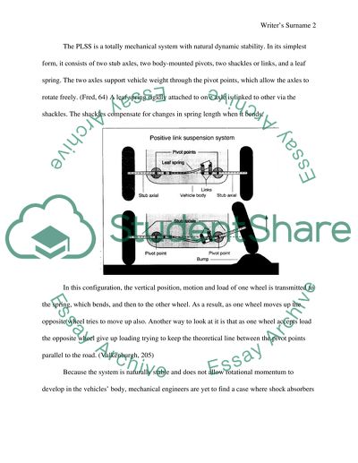
Car Spring Suspension If someone has surveyed the current crop of auto designer, they wouldprobably find a general consensus that the suspension of choice for today’s car and trucks is the fully independent suspension system. (Valkenburgh, 208) It can handle a variety of speeds and road conditions, from bumpy country lanes to superhighways, and can be found on most vehicles sold today. But is it really the best? Many components added to modern independent suspension system are designed to counteract its inherent defects. To offset these deficiencies, designers over the years have added heavy duty shock absorbers, torsion bars, and a host of other devices. In high speed applications, for instance, Indy 500 racing competitors have taken steps such as limiting the suspension travel to compensate for the behavior of independent suspension. (Staniforth, 104) An alternative system that offers several possible advantages has been developed and patented by car engineer that is called the positive linked suspension system (PLSS), it is the product of several years of hard work and several false stars for engineering companies. Now it forms the heart of Tech-Engineering‘s kit vehicle, a Honda-powered tricycle. (Fred, 60) Birth of a spring The PLSS is a totally mechanical system with natural dynamic stability. In its simplest form, it consists of two stub axles, two body-mounted pivots, two shackles or links, and a leaf spring. The two axles support vehicle weight through the pivot points, which allow the axles to rotate freely. (Fred, 64) A leaf spring rigidly attached to on e axle is linked to other via the shackles. The shackles compensate for changes in spring length when it bends. In this configuration, the vertical position, motion and load of one wheel is transmitted to the spring, which bends, and then to the other wheel. As a result, as one wheel moves up the opposite wheel tries to move up also. Another way to look at it is that as one wheel accepts load the opposite wheel give up loading trying to keep the theoretical line between the pivot points parallel to the road. (Valkenburgh, 205) Because the system is naturally stable and does not allow rotational momentum to develop in the vehicles’ body, mechanical engineers are yet to find a case where shock absorbers would be required. Vertical disturbances are self-damped by out of phase load inputs to the leaf spring. The spring acts as a mechanical interrupter and the rate and amplitude of the system’s response is controlled by adjusting the spring rate and the system’s geometry. Because a leaf spring has an almost linear spring rate no matter how much it is flexed, the system’s response can be adjusted by changing the spring material, length or cross section. The axle lengths, both inside and outside the pivot points are in effect, the system’s gain adjustment. Increasing the spring rate of a given PLSS will increase the response rate of the system because the system will transfer more load with less spring deformation. By the same token, shortening the stub axle without changing the spring amplifies the deformation caused by a given wheel movement, increasing the response rate of the system. So, for a softer ride a weaker spring or longer stub axles are used. Adjusting these two variables creates a wide range of ride qualities. The PLSS is also unique in that it does not affect steering forces. Conventional suspension transfers the entire load from one wheel to other via body (tilting it) body roll. PLSS eliminates body roll. And since roll over all a result of high centrifugal forces and the angular momentum due to body roll, PLSS-Equipped Vehicles would be able to take a turn faster without rolling over. With its lack of shock absorbers, along with no electric or hydrologic components the PLSS is simpler, requiring fewer parts than a fully independent system. And, according to the inventor it provides a naturally stable, fully stable and self damped system adoptable for the front or rare wheels in front, rare, or four wheel drive suspensions. It also offer superior cornering and because it is more sure-footed and stable than conventional systems, greater safety to everyday drivers. It may well turn out to be the standard arrangement in the same sense as the self-governing suspension of today. To prove the concept a test vehicle was built. Three wheels and a concept Although designed for four-wheel vehicles, it was decided to initial ally install a suspension in a three wheeled car motor cycle hybrid a worst case configuration to properly test its performance. The three wheel design eliminates any roll stabilizing in puts from rear suspension. And mating the front end with it composite body and PLSS to a motor cycle frame (minus the fork and carrying the engine and single wheel rear suspension) made all over design easier than starting from scratch. Although it is only powered by a 16 hp Briggs engine, the test vehicle reaches 70 mph and demonstrates the new suspension system’s capabilities. As expected, the trike’s body shows no appreciable roll in turn. The quicker the automobile goes around a corner, the lower its body moves. And when it comes across a strong side airstream, when passing the on coming truck for example, it does not swing. It ducks. This is a little worrying until somebody gets habitual of driving like that . Although the test trike is small and light weight compared to production car and trucks, Engineers are sure the system can be scaled up for any applications. (Smith, 60) The PLSS is an uncomplicated spring and bunch of various systems and standard physics principles are applied. It was explained that of course when the mass of vehicle increases its components of suspension system would have to become larger. The flash of inertia of the spring cross-section would have to augment according to the weight but, for the reason that the moment of inertia involves exponential terms it is not a direct one- for- one raise. For comparison, a test car uses a quarter inch thick spring to carry 350 pounds. A similar system for a 4000 pounds load would require a half inch thick spring. Manufacture of Car Spring Suspension A procedure for the manufacture of a coiled spring with an elevated fatigue strength for usage as a car suspension spring is with the help of a bar of tensile potency 1910 to 2020 N/mm2 and a wideness of 8 to 17 mm. In case of a cold coiling step, the rod is converted into shape of a coil. Then the following step is its Annealing that take away strains that appear at the inner side of the coil all through the coiling step. Then a hot setting step of making use of additional heat out of the annealing step and application of a certain amount of load to the coil in order to compress it for a fixed period of time is done. Subsequent to that, with the coil multi-stage shot peening is accomplished. From Test Bed to Kit Car Armed with these test results mechanical engineers started the patent process and tried to increase a major auto companies in his idea. At ford, they ran in to and impenetrable bureaucracy in attempting to present their own concept. Engineers recall while waiting to secure their patent until approaching them again, they continued working on the test car. Eventually they had tweaked the three wheeler into handing like a sports car somewhere along the line they hatched the idea of developing the test car into a kit car. (Technically, the vehicle is a motorcycle, based on its three wheels configuration) Its body is an all composite structure made with poly styrene foam sandwiched between fibre glass. The resin, shell 815 with 306 hardener, it is a true proxy not a polyester resin. Polyester resins attack polystyrene foam. Future molded bodies should be available in several different configurations. The frame is welded steel tube and power is supplied by a water- cooled shaft- driven Honda GL 500 (500cc) The motorcycle that makes up the rear half of this car required a few alterations. The front fork and wheel assembly is removed and the exhausted system modified to clear the vehicle’s frame then the gear shift lever is altered to accommodate a remote shifter. Air scoops on each side of the car provide outside air directly to the motor cycles radiator. (Smith, 60) Inside, heat is supplied by a unit built to warm the rear of large vans and instruments are those removed from the motor cycles expect for the speedometer. A small, electrically driven, retractable wheel built into the frame provides a reverse gear. Mechanical Engineers intend to sell plans for building the body, frame and suspension. According to engineers its body can be built with in two months working nights and weekend. It is also planned to make their completed bodies available as well. Fabricators have been lined up to manufacture the frame and suspension, so when plans are released prefabricated systems should be available also. They have estimated a pre fabricated frame and suspension, less tires and wheels, should cost roughly 2500 dollars and a home built body has material cost about 500 dollars. The motor cycle provided by a buyer, can be one of several water cooled models. Works Cited Fred. P (2004) ‘How to make your car handle’ HP Books. Pg 56-70 Smith. C (2005) ‘Tune to Win’ UK Publishers. Pg 56- 78. Staniforth. A (2006) ‘Competition Car Suspension’ Haynes Publishing, pg 101-115 Valkenburgh. P. V (2004) ‘Race Car Engineering’ HP Trade pg 200-210 Website, www.local.tirereview.com (2008) Read More
Cite this document
  • APA
  • MLA
  • CHICAGO
(Car Spring Suspension System Report Example | Topics and Well Written Essays - 1500 words, n.d.)
Car Spring Suspension System Report Example | Topics and Well Written Essays - 1500 words. https://studentshare.org/design-technology/1563846-car-spring-suspension
(Car Spring Suspension System Report Example | Topics and Well Written Essays - 1500 Words)
Car Spring Suspension System Report Example | Topics and Well Written Essays - 1500 Words. https://studentshare.org/design-technology/1563846-car-spring-suspension.
“Car Spring Suspension System Report Example | Topics and Well Written Essays - 1500 Words”. https://studentshare.org/design-technology/1563846-car-spring-suspension.
  • Cited: 0 times

CHECK THESE SAMPLES OF Car Spring Suspension System

Recumbent Tricycle for Disabled User

It will specifically endeavor to examine the design and manufacture of the suspension system of the recumbent tricycle especially designed to be driven single-handed.... hellip; Full suspension is integrated into the proposed recumbent tricycle for single–handed users; this means that it has a front and rear suspension system.... The front suspension will simply make use of the front fork suspension common in other bicycles and tricycles....
19 Pages (4750 words) Research Paper

Coil Spring Failure

The breakage also occurs due to decrease in hydraulic pressure which may cause the springs to come in to contact with other suspension components, or exhaust components break lines leading to breakage of the coil spring.... The fracture can be caused by riding on a blown out tire that exposes the vehicle springs and other suspension components in to direct contact with roadway making the suspension component to be stressed beyond normal limits leading to fracture....
7 Pages (1750 words) Assignment

Automotive Suspension

hellip; Generally, the suspension system serves to ensure that the automobile maneuver on the surface is facilitated through an efficient control design that takes care of the terrain or road nature.... In such an aspect, the automobile suspension system enables the body of the automobile to be protected against various movement positions that can damage its condition.... The braking system is also part of the larger suspension system since it enables the control of the vehicle through the wheel control....
9 Pages (2250 words) Coursework

Automotive Coil Spring

"Automotive Coil Spring" paper examines the function of a coil spring in the context of an automotive suspension system, the service conditions that the coil spring must withstand, the material property requirements for the coil spring, and reviews the selected manufacturing route in detail.... The coil spring is part of the suspension system and aids in the above functions.... The shock absorbers are put in the front suspension system to inhibit the oscillations of the coil springs....
10 Pages (2500 words) Assignment

Mass Spring Damper System

An MSD system is used for analyzing the dynamics of mechanical systems including the analysis of the dynamic stability of an aircraft and analysis of the dynamics of the suspension system of automobiles (Hinrichsen and Pritchard 16 & Yechout and Morris 303).... This project "Mass Spring Damper system" seeks to employ the decaying curve method to determine the damping coefficient, C, of various mechanical viscous damping systems (dashpots).... nbsp;An MSD system is a crucial engineering component requiring critical understanding....
10 Pages (2500 words) Assignment

Design and Analysis of a Motorcycle Rear Suspension

In the design of the system, the dimensions of the Motorcycle Rear Suspension is significant.... … The paper "Design and Analysis of a Motorcycle Rear suspension" is an outstanding example of an assignment on engineering and construction.... For any motorcycle move, well rear suspension should be designed and modeled so that the user can use less force and withstand all conditions.... The paper "Design and Analysis of a Motorcycle Rear suspension" is an outstanding example of an assignment on engineering and construction....
7 Pages (1750 words) Coursework

Matlab SimMechanics: Double Mass Spring Damper

The stiffness constant is taken as 160000 N/m(K2) for both springs, the damping constant of suspension system as 400 N.... The stiffness constant is taken as 160000 N/m(K2) for both springs, the damping constant of suspension system as 400 N.... The paper has studied the effects of increasing weight on the suspension system.... /s(c2)Damping constant of suspension system =12000 N.... /s(c1)Spring stiffness constant =70000 N/m(K1)Tire stiffness constant (k) =70000 N/m(K2)Mass (sprung mass) (m1) =1500 KgMass (m2) =500 KgSimulink Model Of The SystemThe figure shows Simulink model for Double Mass Spring Damper built for this case Figure 2: Simulink model for Double Mass Spring DamperThis is an Open-Loop Response and it can be seen that to improve the response of Double Mass Spring Damper is changing Damping constant of suspension system....
3 Pages (750 words) Essay

Conventional Quarter-Car Rig

or suspension and tire, equivalent springs will normally be used and these are unlikely to have equivalent non-linear characteristics or the linear characteristics may not be represented in the entire range of the test operation.... There is likely to be a gross error in representing the actual vehicle due to these deficiencies together with the suspension geometry being either simplified or altogether eliminated.... onventional quarter-car rigThe simplified quarter-car test rig is shown in figure 1where it can be observed that the suspension is represented wholly by having a set of air springs....
7 Pages (1750 words) Report
sponsored ads
We use cookies to create the best experience for you. Keep on browsing if you are OK with that, or find out how to manage cookies.
Contact Us