StudentShare
Contact Us
Sign In / Sign Up for FREE
Search
Go to advanced search...
Free

High Bypass Gas Turbine Engine - Coursework Example

Cite this document
Summary
In the paper “High Bypass Gas Turbine Engine” the author explains the 5 basic modules with a detailed description of the operation of each. There is a rise in pressure and fall in the velocity of air to subsonic speeds due to the generation of the shock wave…
Download full paper File format: .doc, available for editing
GRAB THE BEST PAPER98.5% of users find it useful
High Bypass Gas Turbine Engine
Read Text Preview

Extract of sample "High Bypass Gas Turbine Engine"

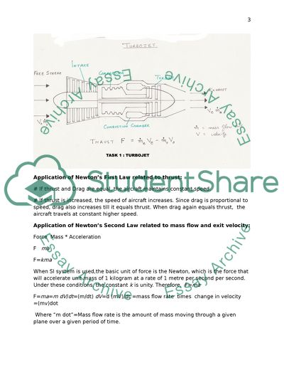
 High Bypass Gas Turbine Engine Application of Newton’s First Law related to thrust: # If thrust and Drag are equal, the aircraft maintains constant speed. # If thrust is increased, the speed of aircraft increases. Since drag is proportional to speed, drag also increases till it equals thrust. When drag again equals thrust, the aircraft travels at constant higher speed. Application of Newton’s Second Law related to mass flow and exit velocity: Force Mass * Acceleration F ma F=kma When SI system is used,the basic unit of force is the Newton, which is the force that will accelerate unit mass of 1 kilogram at a rate of 1 metre per second per second. Under these conditions, the constant k is unity. Therefore, F=ma F=ma=m dV/dt=(m/dt) dV=d (mV)/dt =mass flow rate times change in velocity =(mv)dot Where “m dot”=Mass flow rate is the amount of mass moving through a given plane over a given period of time. Mass flow rate=r * V * A where r is the density and V is the velocity of the fluid passing through area A. This is denoted as m dot (m with a little dot over the top) m dot= r * V * A If we denote exit of the turbojet by ‘e’ and free stream by ‘0’, then we get, F= (m dot*V)e-(m dot *V)0 Thus by maintaining the exit velocity at much greater values than the velocity at intake, high thrust can be produced in turbojet engines (High Exit Velocity). Application of Newton’s Third Law related to thrust: Thrust is the reaction force developed in the forward direction by accelerating a mass of fluid or gas backwards to the rear of the engine. The turboprop propulsion system consists of a core engine and a propeller. The general principles in Application of Newton’s First Law and Third Law in Turboprop engines are the same as given in Turbojet engine. Application of Newton’s Second Law related to mass flow and exit velocity in Turbo Prop: The general thrust equation is F= (m dot*V)e-(m dot *V)0 This means that if the exit velocity is maintained at a higher value than free stream velocity, and simultaneously, the engine flow rate (m dot) is kept as high as possible, the high engine flow will produce a high thrust in a turboprop engine. Even though a large amount of air is ingested, the change in velocity is very minimal between the intake and the exit so that the exit velocity is at a low value (Low exit velocity). Due to the large value of m dot, a high thrust is developed. Total Thrust= Thrust of Propeller Thrust of Core If we denote the free stream conditions by “0”, the propeller exit conditions by “1”, core exit conditions by “e” and core entrance conditions by “c”, then from the basic thrust equation we get: F=(m dot)0 * V1 – (m dot)0 * V0 + (m dot)e * Ve – (m dot)c * V1 In Turboprop engine, the mass flow rate through the propeller is much greater than that of core engine(High mass flow ). The mass flow rate entering the core is almost equal to the mass flow rate exiting the core. The exit velocity from the core is almost the same as inlet velocity into the core(Low exit velocity). Hence the thrust equation can be rounded off to get: Thrust F=(m dot)0 * (V1-V0) + (m dot)e * (Ve-V1) High Bypass Gas Turbine Engine: The 5 basic modules- Along with a Detailed Description of operation of each. Inlet Components and Purpose: The intake also called the inlet serves three purposes, namely (1) recovering as much of the total pressure of the free air stream required for combustion, from free-stream conditions to the conditions and deliver this pressure to the entrance of fan or compressor, (2) delivering air to the compressor under all flight conditions with minimum turbulence and (3) to have minimum drag. The inlet is generally not defined by any particular part, but is formed by structural support parts which are located in front of compressor. The design of subsonic inlet differs from that of supersonic inlet. In subsonic inlets of engines fitted in nacelles air enters in different streamline patterns at different speeds of operation as shown in Fig-1 (Mattingly,p759). Supersonic inlets are designed to provide a air over a wider range of flight conditions than subsonic inlets, including deceleration of air flow due to shock waves. Based on the location of the supersonic compression wave system, supersonic inlets are classified into three types namely, the internal compression inlet, the external compression inlet and the mixed compression inlet. Duct pressure & speed changes: At or near the speed of sound, sonic shock waves are developed which can result in high duct losses in pressure and airflow and also vibrating conditions in the inlet. The inlet has to slow down the air entering the compressor to subsonic velocity. The inlet duct is designed to keep shock waves away from the duct by provision of a spike which creates shock waves in front of inlet duct as in Fig-2(Thaitechnics, 2001)). There will be a rise in pressure and fall in velocity of air to subsonic speeds due to the generation of the shock wave. At higher velocities the Mach number reaches higher values and normal shock waves cause drastic reduction in total pressure recovered by the inlet duct and oblique shock waves are used to further reduce the velocity which is again reduced to subsonic before the air is delivered to the compressor by a normal shock wave. Every decrease in velocity is accompanied by an increase in pressure and or rise in temperature. Ram effect: With increase in speed of aircraft, more air gets filed in the divergent inlet duct. This results in an increase in pressure and decrease in velocity, simultaneous with the air molecules developing impact force. A pileup of molecules soon follows inside the restricted inlet space due to its confined nature, with resultant increase in density of air. The increased density results in an increase in thrust. The above sequence of events is known as the ram effect. Compressor Types: Compressor can be either of axial flow or of centrifugal (radial) flow type. In axial flow compressor, the air is compressed as it flows along the axis of the shaft towards the rear of the compressor whereas in the centrifugal flow compressor, the air is compressed and accelerated in an outward direction towards the periphery of the compressor by centrifugal force .Both these types of compressors have to draw the air into the engine and squeeze it to provide pressurized air to the combustion chamber and turbine. The compressor runs on mechanical energy provided by the turbine and in turn produces gaseous energy at high temperatures and pressures. Components &purpose: The compressor has to provide the turbine with the required amount of air at very high static pressures. The compressor rotor blades convert mechanical energy into gaseous energy in terms of velocity while the stator blades convert the accelerated velocity to higher static pressure. The efficiency of the compressor is influenced by smoothness of airflow to obtain which all components in the compressor are shaped as airfoils. Compressors are used to make the air flow from a low pressure to a high pressure. Axial flow compressors consist of two components: rotating blades and stationary blades as in Fig-3(McMahon,p123). The compression of air happens through several stages each of which consists of a row of the rotating blades or rotor blades followed by a row of the stationary blades or stator blades. The rotor blades are held in place along the rim of a rotating disc while stator blades are attached to the inner side of the casing of the compressor. The purpose of the rotor is to accelerate the air to high velocities while the purpose of the stator is to decelerate the accelerated air so as to increase its static pressure. Centrifugal flow compressors consist of three components: an impeller, a diffuser and a compressor manifold as in Fig-4(Mc Mahon,p154). The purpose of the impeller is to accelerate the air by its high rotational speed and to guide the air towards the outside of the compressor. The purpose of the diffuser is to convert the kinetic energy of air to potential energy or pressure. Operation of centrifugal: Centrifugal compressors operate by sucking in the air near the hub and rotating it by the action of the impeller. The impeller delivers the air to the diffuser section where the air builds up pressure by losing its velocity. Operation of Axial: The air flow takes place through an almost straight path through the engine which results in less loss of energy due to change in direction of flow. The air pressure builds up as the air passes through each stage until it reaches the outlet at very high pressures of up to 70 psi. Axial-flow compressors can be designed with two or more separate compressors to reduce compressor stall risks. Advantages & disadvantages: The main advantage of the centrifugal compressor is that it offers high pressure rise per stage. It is much less expensive than the axial-flow type. The disadvantage of centrifugal compressor is that it has a low efficiency and is economical to use only in small turboprop engines. The main advantage of the axial-flow compressor is its higher peak efficiency due to less energy loss since air flows in a straight path across the compressor. Another advantage is that the air can be compressed in as many stages as the designer desires to get high pressure ratios. A third advantage is that the frontal area and inlet need not be very large and can be kept smaller for the same volume of air being compressed. Explanation of stall &surge: The failure of the compressor blades to move the air at the flow rate for which it was designed is known as a stall. As a result the air velocity in the first stage of compressor decreases to levels low enough to give an angle of attack equal to a stall value. The compressor becomes incapable of compressing any more air for the moment causing interruption in air flow. The air having high pressure suddenly surges forward through the compressor inlet and escapes out through it in a rapid manner, often with a loud banging sound. Flames also accompany the surge and escape in both the forward and backward directions of the engine. The surge happens very rapidly and the compressor recovers within fractions of a second. Sometimes surge results in non-recovery and may also cause permanent damage to the turbine from overheating. Methods of avoiding stall & surge: Compressors are generally designed in such a way as to prevent compressor stall from taking place, by imposing a surge margin as in Fig5 (Kroes and Wild,p293) . Compressor stall can also be avoided by providing variable inlet guide vanes for the first stage of compressor. Variable stator vanes are also provided for the subsequent compressor stages. These variable vanes can be closed progressively when compressor speed is lowered so that a suitable angle of attack can be maintained for the rotor blades. This is achieved by pitch angle control synchronized through the fuel control unit. In this way, possibilities for stall and surge can be minimized. Compressor bleed off valves which vent the compressor are also used to prevent compressor stalls. Combustion Chamber Requirements: The combustion chamber has to mix compressed air with large amounts of fuel and burn the mixture so as to produce hot expanding gases. In addition, it has to provide for controlled release of the heat of burning so as to heat and accelerate the air to produce a smooth and stable stream of gas with minimum pressure loss and maximum release of heat, keeping to the barest minimum the flame contact with metal parts, by using combustion liners. Pressure & velocity changes: When the air has been heated and its internal energy has been increased, its velocity also is increased so as to drive the turbine. In the combustion chamber, this is accompanied by a slight pressure drop with rise in velocity and temperature to the rear. Components & purpose: The main components of the combustion chamber are the inlet diffuser, the dome, the cowl or snout and the liner. Besides, the fuel injector, igniter, burner case, the dome and the primary swirler constitute the subcomponents of the combustor. The schematic representation of combustion chamber is given at Fig-6 (Mattingly,p828). The inlet diffuser reduces the velocity of the air coming out of the compressor exit and delivers this air in a stable uniform flow. The purpose of the snout is to bifurcate the incoming air into primary air and a secondary airflow for cooling, dilution etc. The purpose of the dome is to produce an area of high turbulence and flow shear near the fuel nozzle, to atomize the fuel and to facilitate rapid formation of fuel-air mixture. Process of combustion: During the combustion process, a molecular reaction takes place between the air and the vaporized fuel, the rate of which is dictated by static pressure and temperature. The rate at which the fuel gets vaporized and mixed with the air decides the rate of combustion. To maintain a stationary flame, the velocity of the mixture has to maintain within limits. At very high velocity, the flame gets blown out while at too low a velocity, the flame gets extinguished. A flame holder is used to establish regions of recirculation in the burner and to maintain the flame. Types of combustion chamber: The three types of combustion chambers in use are the Can, the Annular and the Can-annular combustion chambers. In Can combustion chambers, each burner can is a separate combustor having a separate fuel supply. The cans and fitted along the periphery or circumference of the engine. In the Annular combustion chamber, there is only a single but large combustor formed within the engine case within which multiple fuel nozzles burn the fuel in a ring of fire. In Can-annular type of combustion chambers, individual cans with separate fuel nozzles are supplied air from a common annular housing. Advantages &disadvantages: The Can type of combustion chamber facilitates easy replacement but is the efficient and is structurally weak or unstable. The Annular type of combustion chamber is the most efficient, and structurally the strongest but its repair is costly necessitating a complete engine disassembly and replacement. The Can-annular type of combustion chamber is structurally strong and facilitates easy replacement but in efficiency it lies intermediate between Can and Annular types of combustion chambers. Methods for reducing emissions: Co2 and NOx emissions can be reduced by opting for recirculation of exhaust gas. By using annular combustion chambers, a smoke-free exhaust can be obtained. Turbine Types: Turbine are of two basic types: the centrifugal turbine and the axial turbine. Operation of centrifugal: The stators in the centrifugal turbine accelerate the flow and increase the tangential velocity of the gases. The rotors decrease the tangential velocity and remove the energy from the flow. Operation of axial: The axial turbine is the reverse of the axial compressor. The high-pressure high-temperature gas from the combustion chamber is made to impinge the stator blades and gets redirected tangentially to rotor blades. The gases leaving the stator blades get accelerated while their static pressure decreases and the tangential velocity increases. Tangential velocity of gases is decreased by the rotor with the result that a torque is produced on the output shaft accompanied by decrease in static pressure and static temperature. Pressure& velocity changes: The pressure, temperature and velocity of air all decrease in the turbine which extracts energy from the hot high-velocity gases and coverts it to power to drive the shaft. Components & purpose: The purpose of the turbine is to produce usable output power to drive the compressor and engine accessories. Turbine cooling methods: Turbines are fabricated with cooling passages and thermal barrier coatings. Bleed air from the compressor is fed around the combustor and into the turbine blades through the cooling passages to cool the turbines. Air traveling between combustor and outer engine case is used to cool the turbine stator blades. Air routed through inner passageways is used to cool the turbine rotor blades. At least five categories of cooling methods are used in the turbine, which can be termed as convection cooling, impingement cooling, film cooling, full-coverage film cooling and transpiration cooling. Out of these categories, transpiration cooling is unique in that the component to be cooled is made with a porous surface through which a cooling fluid is made to effuse from inside to outside forming a protective layer around the surface of the component. Computational Fluid Dynamics and Finite Element Analysis are employed for accurate determination of metal temperatures required during design of turbine cooling methods. Tip clearance control: Turbine tip clearances are determined by the difference in thermal expansion of turbine casing assembly and turbine rotor assembly. This has to be kept minimal for maximum efficiency since larger tip clearances would result in leakage of more gas and hence loss of power produced by the turbine while too small a clearance would result in fouling of turbine rotor blades with the casing. Through accurate thermal modeling and by controlling the turbine case temperature modulated or semi-modulated case cooling technology turbine tip clearance can be optimized. Exhaust Types: Exhaust nozzles are of two types: the convergent nozzle and the convergent-divergent (C-D) nozzles. Variable-area exhaust nozzles are used on engines with thrust augmentation systems such as afterburners. Pressure & velocity changes: At the exhaust, an expansion of gases takes place with decrease in temperature and pressure. At the nozzle, a high exit velocity is developed due to the convergent shape of the propelling nozzle. The exit velocity reaches the speed of sound and the nozzle gets choked, with no further increase in velocity which results in buildup of static pressure to above the atmospheric pressure Convergent/Divergent: The convergent divergent (C-D) nozzle or venturi consists of a convergent duct followed by a divergent duct with a throat at the narrow region. The CD nozzle is used to obtain the maximum conversion of energy in the combustion gases to kinetic energy. REFERENCES Kroes,M.J and Wild, T W “Aircraft Power Plants” 2010, New Delhi Mattingly,D, J. “Elements of Gas Turbine propulsion” 1996. Mc graw-Hill Inc. New Delhi Mc Mahon P J “ Aircraft Propulsion” 1971 Sir Issac Pitman And sons Ltd, London NASA websites available at(1) http://www.grc.nasa.gov/WWW/K-12/airplane/turbth.html (2) http://www.grc.nasa.gov/WWW/k-12/airplane/turbprp.html (3) http://www.grc.nasa.gov/WWW/k-12/airplane/turbfan.html Thaitech, 2001 [online] available at http://www.thaitechnics.com/engine/engine_construction.html, accessed on 31-12-2011 Read More
Cite this document
  • APA
  • MLA
  • CHICAGO
(“High Bypass Gas Turbine Engine Coursework Example | Topics and Well Written Essays - 2000 words”, n.d.)
High Bypass Gas Turbine Engine Coursework Example | Topics and Well Written Essays - 2000 words. Retrieved from https://studentshare.org/physics/1440140-gas-turbine-engine-basics
(High Bypass Gas Turbine Engine Coursework Example | Topics and Well Written Essays - 2000 Words)
High Bypass Gas Turbine Engine Coursework Example | Topics and Well Written Essays - 2000 Words. https://studentshare.org/physics/1440140-gas-turbine-engine-basics.
“High Bypass Gas Turbine Engine Coursework Example | Topics and Well Written Essays - 2000 Words”, n.d. https://studentshare.org/physics/1440140-gas-turbine-engine-basics.
  • Cited: 0 times

CHECK THESE SAMPLES OF High Bypass Gas Turbine Engine

Gas turbine engine basics

Therefore, F=ma The turboprop propulsion system consists of a core engine and a propeller.... The general principles in This means that if the exit velocity is maintained at a higher value than free stream velocity, and simultaneously, the engine flow rate (m dot) is kept as high as possible, the high engine flow will produce a high thrust in a turboprop engine.... If we denote the free stream conditions by “0”, the propeller exit conditions by “1”, core exit conditions by “e” and core entrance conditions by “c”, then from the basic thrust equation we get: In Turboprop engine, the mass flow rate through the propeller is much greater than that of core engine(High mass flow )....
8 Pages (2000 words) Coursework

Detailed Cycle Analysis of Turbofan Engine

Turbofan is simply a gas turbine engine and a ducted fan.... The gas turbine… The ducted fan accelerates the air rearwards.... Fan – The fan is at the obverse of the engine.... The fan initiates a flow of air around the engine.... The bypass air usually keeps the engine quieter, cooler and more fuel efficient.... The two whirling turbines rotate the shafts that steer both the fan and the compressors at the front part of the engine....
8 Pages (2000 words) Essay

Key Aspects of the Jet Engines

A jet engine is a gas turbine engine that is a type of internal combustion engine.... he main parts of the jet engines or gas turbine engine are turbine, compressor, fuel ignition system, and a connecting rod that connects the turbine and compressor.... Jet engines are efficient and have more power to weight ratio as compared to any other type of engine.... Fuel and air are mixed and ignited inside the cavity of the engine....
8 Pages (2000 words) Coursework

Jet Propulsion as a Means of Air Travel

The author using Brayton's Thermodynamic Cycle shows that the Turbofan jet engine of today is the most efficient and cost-effective source of power for long-range air travel.... hellip; For an isentropic flow of a perfect gas, several relations can be derived to define the pressure, density, and temperature along a streamline, which is vital in the aero- and thermodynamics of jet flights, making the jet engine the most widely used mode of the three types of propulsion systems available for aircraft....
15 Pages (3750 words) Research Paper

SCRAMJET - Engines for Planes and Rockets

The first jet engine in the form of the turbojet engine was developed in 1930, but the jet engine was to take several years more before it became commercially useful as a propulsion system for airplanes.... Hans von Ohain and Sir Frank Whittle working separately are credited with the invention of the jet engine.... By 1939 the first airplane using a turbojet engine for propulsion took to the air, while the first jet to fly using the jet engine developed by Frank Whittle took to the skies in 1941....
20 Pages (5000 words) Article

Gas Turbine Engine Configuration

The paper "gas turbine engine Configuration" describes that gas turbine engines are the most versatile type of internal combustion engines.... A simple gas turbine engine has four most important parts.... A gas turbine engine is totally an internal combustion engine that burns the fuel to extract the chemical energy stored in the fuel.... A gas turbine engine has no cavity that could be named piston.... Thrust is the amount of force that is the output power of the gas turbine engine and it is responsible for the motion of aircraft, etc....
6 Pages (1500 words) Essay

Performance Deterioration of Gas Turbine Engines

This gives an example of how performance degradation is linked to the mechanical behavior and consistency of a gas turbine engine.... The paper "Performance Deterioration of gas turbine Engines" investigates the prognostic methodology that will be able to determine and predict degradation as a single parameter.... hellip; Compressor fouling and its limitations are the most predominant area that heavily influences gas turbine deterioration.... he use of high-performance gas turbine engines has increased fuel costs making it essential for maintaining high working efficiencies of the engines....
6 Pages (1500 words) Research Paper

Engine Selection Parameters

The author of the "engine Selection Parameters" paper elaborates on key parameters that are used in the process and procedures during the selection of the superlative engine for the aircraft.... Thrust-to-measure is termed as a ratio is the ratio of thrust to weight of a jet engine, propeller locomotive.... It is a dimensionless quantity and is an indicator of the performance of the engine.... n the other hand, an undersized engine can be overstressed at each of the key throttle points while performing so that the service life will be reduced....
6 Pages (1500 words) Term Paper
sponsored ads
We use cookies to create the best experience for you. Keep on browsing if you are OK with that, or find out how to manage cookies.
Contact Us