StudentShare
Contact Us
Sign In / Sign Up for FREE
Search
Go to advanced search...
Free

Transmission Electron Microscopy - Coursework Example

Cite this document
Summary
This essay analyzes Transmission Electron Microscopy, that has revolutionized the field of microscopy, touching a variety of aspects, both biological and physical. TEMs comprise a range of different instruments that make use of the properties of electrons, both as particles and as waves…
Download full paper File format: .doc, available for editing
GRAB THE BEST PAPER93.1% of users find it useful
Transmission Electron Microscopy
Read Text Preview

Extract of sample "Transmission Electron Microscopy"

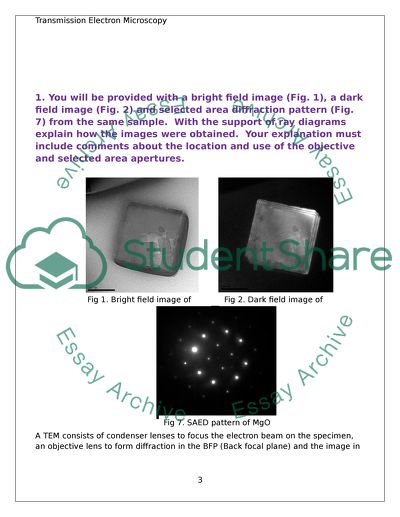
? Transmission Electron Microscopy has revolutionized the field of microscopy, touching a variety of aspects, both biological and physical. Transmission Electron Microscopes (TEMs) comprise a range of different instruments that make use of the properties of electrons, both as particles and as waves. The TEM generates a tremendous range of signals so we can obtain images, DPs and several different kinds of spectra from the same small region of the specimen (Williams and Carter 2009). The working principle of a TEM is that when electrons are accelerated up to high energy levels and then focused onto a specimen, they scatter or backscatter elastically or in-elastically, producing many different interactions that are a source of signals like X-Rays and light, enabling magnification and visualization of ultra-microscopic particles and micro-organisms. 1. You will be provided with a bright field image (Fig. 1), a dark field image (Fig. 2) and selected area diffraction pattern (Fig. 7) from the same sample. With the support of ray diagrams explain how the images were obtained. Your explanation must include comments about the location and use of the objective and selected area apertures. A TEM consists of condenser lenses to focus the electron beam on the specimen, an objective lens to form diffraction in the BFP (Back focal plane) and the image in image plane, and other lenses to magnify the image or the diffraction pattern on screen. In order to obtain images in TEM, we either focus on the central spot (direct beam), or on the scattered electrons (diffracted beam). This is done by inserting an aperture (selected area aperture) into the BFP of the objective lens followed by selecting the appropriate beam. Bright field image (Figure 1) The given micrograph depicts a dark MgO crystal on a light and bright background. The topography on the face of the crystal is very clear. Such an image is called a bright field image and has a very high contrast. The objective diaphragm is placed in the back focal plane and is used to select the transmitted/direct beam. The diffraction pattern, caused by the scattered electrons is blocked, and only the central spot visible through the aperture is selected. It is important to select the direct beam to obtain a bright field image. The parts of the crystal in Bragg orientation appear dark, and the amorphous parts of the crystal are bright. The objective diaphragm is adjusted in such a way that an aperture appears in the back focal plane of the objective lens, allowing only the direct beam to enter and blocking the diffracted beam. The objective aperture, when inserted, controls the collection angle. The placement of the SAD (selected area aperture) is critical as it should be adjusted to obtain only the direct beam in this case. Dark field image (Figure 2) The micrograph in figure two depicts a bright MgO crystal on a dark background. Such an image is obtained by selecting only the scattered electrons using a selected area aperture, enabling them to reach the image plane. The electrons that are not in the direct beam are selected to form a dark field image. The objective aperture is moved sideways to select the un-scattered electrons. This method is of high utility in case of observing certain specific crystallographic orientations of the specimen. The dark field image can also be obtained through another method, called centered dark field operation. In this case, the objective aperture is not shifted and the primary/direct beam is used instead. "The beam is tilted in order to allow only the scattered/diffracted electrons to go through the objective aperture (William and Carter 2009). Selected area diffraction pattern SAED (Figure 7) The given micrograph clearly depicts the symmetry of the lattice of MgO crystal through a selected area diffraction pattern. Selected area diffraction patterns are obtained by inserting the SAD aperture into the image plane of the objective lens and aperture on the optic axis in the middle of the viewing screen (William and Carter 2009). The selected area aperture is used to select one part of the image sample. It is possible to obtain diffraction patterns by using the projector lenses to focus on electron beams to obtain a small spot on the object surface. The spots appear as disks whose radii depend on the condenser diaphragm. Given below are ray diagrams depicting the position of the aperture in order to obtain the bright field image, the dark field image using displaced aperture and the dark field image using centered dark field operation: courtesy- Williams and Carter 2009 Given below is a ray diagram of SAED formation: courtesy- Williams and Carter 2009 2. (a) From a lattice image obtained from a single crystal of BaZrO3 (Fig. 4) determine the magnification. Compare this with the magnification obtained using the scale bar. Calculate the length the scale bar should be. Solution: Given below is the sequential workout for determining the magnification of the given lattice image: Step 1: In order to measure the size of the image, the pixel to cm ratio is calculated. Size of original image= 14.5?14.8 cm (found from image properties) The same size corresponds to 548?559 pixels (after conversion). Therefore, the Pixel to Centimeter ratio is calculated as follows: For height= 548/14.5= 37.79 For width= 559/14.8 = 37.77 Mean ratio= (37.79+37.77)/2= 37.78 pixels per centimeter Step 2: A circle was drawn on the image using Ms Paint, corresponding to 20 nm or 126 pixels on image. Number of lattice spacing of BaZrO3 = 20 Step 3: Calculation of image length: 126 pixels/37.8= 3.33 cm=3.33?107 nm Step 4: Calculation of object length: The lattice spacing of BaZrO3 along {1,0,0} lattice plane is 0.419nm (Yamada et al 2006) Therefore, object length= 0.419?20=8.38 nm Step 5: Calculation of magnification Magnification (M) = Length of image (Li )/Length of object (Lo) = 3.33?107/ 8.38 = 0.39?107 =3.9?106 Therefore, the magnification is found to be 3.9?106 Comparing this with the magnification found with the scale bar: The scale bar corresponds to 126 pixels= 3.33 cm= 3.33?107 nm The scale bar image length is given as = 20 nm Therefore, magnification= 3.33?107/20= 0.166?107= 1.66?106 The magnifications are in the ratio of 3.9?106/ 1.66?106 = 2.3 The length of the scale bar should have been the double of 3.33 cm, i.e. 6.66 cm, to be in agreement with the calculated magnification. 2. (b) Explain the fringes present on the circular ZrO2 grain. The fringes formed on the circular ZrO2 grain in the BaZrO3 crystal are most probably due to the formation of Moire Fringes. This occurs because of difference in lattice spacing of ZrO2 and BaZrO3, caused by large lattice mismatch. 3. (a) You are provided with images with and without condenser astigmatism (Fig. 5 & 6); explain how this aberration may be reduced. If this aberration is not minimised describe the effect this has on high magnification images. The two micrographs above represent condenser astigmatism, which is a chromatic aberration. Figure.5 represents a circular electron beam without condenser astigmatism. Figure.6 represents an elliptical electron beam with condenser astigmatism. Reduction of condenser astigmatism Condenser lens astigmatism distorts an electron beam, making it elliptical on either side of the focus. The condenser astigmatism is corrected by applying correction fields on both X and Y axes. This is done by adjusting the C2 lens, making the image of the beam to expand or contract about its minimum dimension. Because of condenser astigmatism, the image becomes elliptical and rotates 90? on either side of focus. Using condenser stigmators, which help in correction of C1 and C2 lens astigmatism, a compensating magnetic field can be created around the electron beam to prevent astigmatism. By over focusing and under focusing the beam, the stigmator can be adjusted to obtain a circular image (Egerton 2005). Effect of condenser astigmatism on high magnification images Condenser-lens astigmatism does not directly affect the resolution of a TEM-specimen image (Egerton 2005). But if such astigmatism is not removed, the maximum intensity of the image on the screen is reduced, because of uneven distribution of illumination. The brightness and contrast of the image are also affected. This reduces the chances of focusing on the fine details of the image. 3. (b) Compare focussing and removing objective astigmatism by observation of Fresnel fringes vs. observation of the FFT of the image at high and low magnification. No images are supplied for this question, though you may use images from the literature or internet if they are correctly referenced. Objective lens astigmatism occurs if the objective aperture is misaligned, so must always carefully centre the aperture on the optic axis, symmetrically around the electron beam used to form the bright field or dark field image (Williams and Carter 2009). This kind of astigmatism can be detected and removed by observing the Fresnel fringes or fast Fourier transforms. Observation of Fresnel fringes for detection of objective astigmatism These fringes result because of diffraction phenomena, occurring at sharp edges of the specimen when objective lens if under focused or over focused. Fresnel fridge is brighter around the edge of the selected image detail. If it is a hole, the line appears inside. This occurs when the objective lens is under focused, i.e. when the objective lens is weaker than the focus. Fresnel fringe appears as a dark line when the image is over focused, i.e. objective lens is stronger than focus. With a perfectly symmetrical objective lens field, the fringes will be of uniform width. With an asymmetrical (astigmatic) objective lens, the fringes will also be asymmetrical and, close to the focus, part of the hole will have a bright fringe and the other part a dark fringe associated with it. Given below is the correction of objective lens astigmatism by viewing Fresnel fringes. (a) A Fresnel fringe showing asymmetry in width due to astigmatism in the objective lens. (b) Astigmatism corrector switched on. Full strength, arbitrary direction. Note increased astigmatism. (c) Corrector oriented to oppose the astigma-tism of the objective lens. Note that a short length of underfocus fringe now occupies the place of the overfocused fringe in (a). (d) Corrector strength reduced to obtain a uniform fringe. Magnification ~500,000X. Fringe width 0.4nm (Agar 1974) Observation of fast Fourier transforms of the image at high and low magnification for detection and correction of objective astigmatism According to Rickerby et al, the objective lens astigmatism can be determined by taking a fast Fourier transform (FFT) of the amorphous edge of a specimen, the semi-angle of beam convergence, which can be determined directly from the diameter of the disks in the diffraction pattern and the objective aperture radius and position, which can also be determined by using double exposure to photograph of the objective aperture on the diffraction pattern. Although it is possible to quantify the degree of astigmatism in a High resolution TEM image, one ideally tries to eliminate any astigmatism, since it cannot be incorporated into most image simulation programs. The correction of the objective astigmatism by FFT can be done by first finding and focusing on some amorphous material on the TEM sample (amorphous carbon support film, glue line for sandwich cross section or amorphised layer on edge of crystal left from ion bombardment). The magnification is then increased to a very high value, about 135000 X (Alexander 2010). Using computer iterated methods and live Fourier transform; the aberration can then be removed. The image below depicts the correction of objective astigmatism using FFT (courtesy- Alexander 2009) Image after FFT correction 3. (c) Comment on the white fringe surrounding the MgO crystals in Fig. 9. The given micrograph depicts MgO crystals. There are white fringes at the edge of the specimen in the image. These are Fresnel fringes. The presence of these white fringes proves the presence of objective lens astigmatism, caused by under focusing of the objective lens. The correction can be made by adjusting the direction and strength of the objective lens stigmator. 4. (a) From a polycrystalline ring pattern from gold (Fig. 8) determine the camera length. Assume an electron accelerating potential of 200kV. The micrograph in figure 8 shows the diffraction pattern of polycrystalline gold. Camera constant calibration is most often performed by evaporation of gold onto a very thin carbon or formvar film, having a grain size small enough to give continuous ring pattern. The planes of a crystal would diffract electrons if these planes were lying approximately parallel to the electron beam. In case of a specimen containing many crystals of random orientation, the spots on the rings are so close together that the rings appear continuous (Goodhew et al 2001). Calculation of camera length This can be done by using the equation d = L ?/R, where, L = camera length R = ring radius ? = electron wavelength The electron accelerating potential is assumed to be 200kV. Calculation of ? = h/ ?(2Em)= 6.63?10-34/ ? (2?2.0 ?105 ?1.6?10-19?9.11?10-31) [Assuming E= 200keV] = 2.746 ?10-12 m The hkl miller indices and d-spacing values of gold are used to determine the camera length as follows: Gold has the fcc crystal structure with lattice parameter a= 0.4078 nm or 4.078 A. Therefore the rings are indexed as given below:- Gold d-spacing d-spacing Miller indices (hkl) (A) (m) (111) 2.355 2.355?10-12 (200) 2.039 2.039?10-12 (220) 1.442 1.442?10-12 (311) 1.236 1.236?10-12 (222) 1.177 1.177?10-12 The diameters of the spectra in the image are measured in pixels and converted to cm and m as follows: Ring Diameter (pixels) Radius (pixels) Radius (cm) Radius (m) L = d ? R/? (m) 1st ring 91 45.5 1.20 0.012 1.02 2nd ring 107 53.5 1.41 0.014 1.03 3rd ring 150 75 1.98 0.019 0.99 4th ring 176 88 2.32 0.023 1.03 5th ring 234 117 3.09 0.030 1.93 Mean of all the values (L) = 1.2 m The average camera length is found to be 1.2 m. 4. (b) Use the calculated camera length to index the SAED spot pattern in Fig. 7. The given SAED pattern represents body centered cubic crystal structure. Therefore, the value of the BCC h + k + l = even. The miller indices (hkl) are (110), (200), (211), (220), (310) and (222). R1 was measured as 280 pixels = 7.4cm= 0.074 m Using the equation, d = L ?/R, the d is computed as follows: d1 = 1.2?2.746?10-12/0.074 = 44.5?10-12 m= 0.445 A= 0.45 A, which corresponds to miller index [1 1 0] The lattice parameter is calculated as follows: d= a/ ?(h2+K2+l2) 0.45 ?10-10 = a/ ?(12+12+02) Therefore, a= 0.45 ?10-10 ? ?(12+12+02) = 0.45 ?10-10 ? ?2= 6.2 A The d-spacing of the other indices are then calculated as follows: 4. (c) From the pattern just indexed determine the zone axis. The zone axis is calculated by t aking the vector cross product of any of the two miller indices as follows: (110) ? (200) = = 0i-0j-2k = (0, 0,-2) Agar, Alan W., Ronald H. Alderson, Dawn Chescoe. Principles and practice of Electron Microscope operation. New York: North-Holland Publishers, 1974. Alexander, Duncan. "CM20 User Guide". Ecole Polytechnique Federale De Lausanne, 2010. Egerton, Ray F. Physical Principles of Electron Microscopy: An Introduction to TEM, SEM, and AEM. New York: Springer Science, 2005. Goodhew, Peter J., F. J. Humphreys, R. Beanland. Electron microscopy and analysis. New York: Springer Science, 2001. K. Yamada, A. Ichinose, Y. Shingai, K. Matsumoto, Y. Yoshida, S. Horii, R. Kita, S. Toh, K. Kaneko, N. Mori, M. Mukaida, "TEM observation of ErBa2Cu3O7-[delta] films with BaZrO3 artificial pinning centers", Advanced Superconductivity 18 (2006): 660-66, doi: 10.1143/JJAP.47.899 McLaren, Alex C. Transmission Electron Microscopy of minerals and rocks. London: Cambridge University Press, 1991. Williams, D. B., and C. B. Carter. Transmission electron microscopy: a textbook for materials science. New York: Springer, 2009. Read More
Cite this document
  • APA
  • MLA
  • CHICAGO
(“Transmission Electron Microscopy Coursework Example | Topics and Well Written Essays - 3000 words”, n.d.)
Retrieved from https://studentshare.org/physics/1423548-transmission-electron-microscopy
(Transmission Electron Microscopy Coursework Example | Topics and Well Written Essays - 3000 Words)
https://studentshare.org/physics/1423548-transmission-electron-microscopy.
“Transmission Electron Microscopy Coursework Example | Topics and Well Written Essays - 3000 Words”, n.d. https://studentshare.org/physics/1423548-transmission-electron-microscopy.
  • Cited: 0 times

CHECK THESE SAMPLES OF Transmission Electron Microscopy

Low Voltage Scanning Electron Microscopy

In the paper “Low Voltage Scanning electron microscopy” the author examines low voltage scanning electron microscopy, which denotes the use of scanning electron microscopy and uses few kilo electron-volts (<5 keV) for accelerating the electron beam used in scanning.... Working Principles of Scanning electron microscopy (SEM) Scanning electron microscopes (SEMs) are microscopes, which produce sample images by scanning the samples using a beam of focused electrons....
7 Pages (1750 words) Research Paper

Soil and Microbes

Epifluorescence Microscopy [EFM] and Transmission Electron Microscopy [TEM] using two elution buffers (1% potassium citrate and 10Mm Sodium pyrophosphate) (Sampling Natural Viral Communities from Soil for Culture-Independent Analyses by Kurt E.... In microscopic methods plus culturing the soil samples are impregnated with agar or polyacrylate resins and sectioned into thin plates and examined by direct microscopy.... Once the excess FITC-antibody conjugate is washed and removed, only those microbial cells will fluoresce, can be located and identified by epifluorescence microscopy....
5 Pages (1250 words) Essay

Phase Contrast Imaging

Phase Contrast imaging, which is informally known as High Resolution or HR imaging, is a process of imaging in Transmission Electron microscopy, and is one of the chief components that discriminates Transmission Electron microscopy from traditional optical microscopy.... Moreover, phase contrast microscopy produces high-contrast images of transparent samples such as cells or micro-organisms (Murphy, 2002)....
15 Pages (3750 words) Thesis

Organic solar cells

In the study of organic solar cells, the functions, the structure, development and advancements in terms of the theoretical and applied technologies based on empirical studies and research are important in the field. The development of solar cells is undertaken to answer the… In such case less harm can be achieved due to the production of electricity even without the release of carbon dioxide and greenhouse gases....
5 Pages (1250 words) Literature review

Answering Questions - General Biology

ransmission electron microscopy D.... The paper "Answering Questions - General Biology" highlights that the hydrogen bonds link the bases of DNA because they allow easier DNA strand separation compared to other types of bonds and allow the process of transcription to begin, which is the first step in the central dogma of biology… Which of the following type of microscopy would be most effective in visualizing the fine structure of viruses and cytoskeletal filaments 10–25 nanometers in diameter?...
2 Pages (500 words) Assignment

Life cycle of malaria

Transmission Electron Microscopy that gives detailed pictures of each phase (Kakkilaya, n.... Intravital microscopy that allows direct visualization of the plasmodium cell movement in the host.... “Tracking a Killer; In Vivo microscopy Reveals Details on the Life Cycle of Malaria Parasites.... One, it aids researchers in the design and implementation of interventions that can be used to hinder transmission, infection and develop Malaria treatments....
1 Pages (250 words) Outline

The Impact of Fruit Juice on Human Teeth

The author of the following research paper "The Impact of Fruit Juice on Human Teeth" underlines that dental erosion or enamel erosion is a common health problem.... Several studies have been conducted to evaluate the cause, progression, detection, and management of dental erosion.... hellip; The changing lifestyle pattern of human beings which incorporates consumption of acidic substances like soft drinks and fruit juices has been a major contributor to the development and progression of dental erosion....
16 Pages (4000 words) Research Paper

The Principles and Types of Electron Microscope

The paper "The Principles and Types of Electron Microscope" states that both Scanning Electron Microscopy and Transmission Electron Microscopy are used scientifically and industrially.... hellip; In dark-field electron microscopy, the angle upon which bombardment of the electron beam is tilted in the darker field to produce brighter spots mainly to determine whether there exist crystalline structures within the specimen.... The electron beam used in the electron microscopy is much shorter wavelengths thus allow a higher degree of resolution as well as high contrast....
6 Pages (1500 words) Essay
sponsored ads
We use cookies to create the best experience for you. Keep on browsing if you are OK with that, or find out how to manage cookies.
Contact Us