StudentShare
Contact Us
Sign In / Sign Up for FREE
Search
Go to advanced search...
Free

Mohrs Circle and Strain Gauge Rosette - Lab Report Example

Cite this document
Summary
From the paper "Mohr’s Circle and Strain Gauge Rosette" it is clear that the errors are tolerable, as the units in microstrains are minute, and when rounded off would, for practical purposes, be useful in providing information on the beam’s tensile strength…
Download full paper File format: .doc, available for editing
GRAB THE BEST PAPER92.5% of users find it useful
Mohrs Circle and Strain Gauge Rosette
Read Text Preview

Extract of sample "Mohrs Circle and Strain Gauge Rosette"

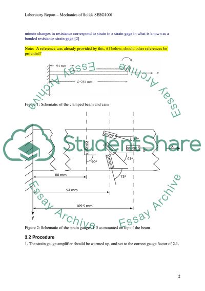
Mohr's Circle and Strain Gauge Rosette Your Discipline (Mech, Aero, Ship) Summary Introduction Mohr's circle is a graphical method to determine the effect of a coordinate rotation on a tensor quantity. In the engineering sciences it is applied to analyse the effect of a coordinate rotation on stress, strain, second moment of area and moment of inertia. In this experiment, mechanical estimations of the principal strains as well as the direction of maximum strain shall be effected through the use of readings derived from a strain gauge rosette, and the resultant construction of the Mohr's Circle. The Mohr's Circle will provide the visual means by which the principal strains may be graphically estimated and assessed for accuracy by comparing the results derived therefrom to results computed by theoretical means. 2 Objectives The objectives of this experiment are: 2.1 To apply the 3-gauge rosette to an aluminum alloy beam subjected to biaxial strains; 2.2 To obtain readings from the three gauges, and to construct a Mohr's circle corresponding to the readings; 2.3 To set up and gather direct readings from two gauges set parallel to each of the axes (horizontal and vertical) along the test plane; 2.4 To compare the values for the principal strains derived from the Mohr's circle for the 3-gauge rosette, and those derived from the horizontal and vertical gauges; and 2.5 To compare the values derived mechanically from the gauge readings from those derived theoretically, as an indication of accuracy, and to explain the discrepancies between them. 3 Experimental 3.1 Apparatus An aluminium alloy beam, clamped at one end within a rig containing a cam whose full-range rotation leads to a repeatable tip deflection of = 0.5" = 12.7 mm, as shown in Figure1. The beam has dimensions as follows: breadth b = 25.4 mm, depth d = 6.35 mm and length (to the cam) L = 254 mm. Three strain gauges are mounted on the upper surface at 94 mm from the clamped end; these gauges are mounted at 15, 45, and 75 with respect to the longitudinal, x-axis, of the beam, as shown in Figure 2. Each of these gauges can be selected using a switchboard, to be one arm of a Wheatstone bridge arrangement [1 research and give reference ], with a dummy strain gauge providing temperature compensation. The Wheatstone bridge is a divided bridge circuit used to measure electrical resistance; these minute changes in resistance correspond to strain in a strain gage in what is known as a bonded resistance strain gage [2] Note: A reference was already provided by this, #1 below; should other references be provided Figure 1: Schematic of the clamped beam and cam Figure 2: Schematic of the strain gauges 1-5 as mounted on top of the beam 3.2 Procedure 1. The strain gauge amplifier should be warmed up, and set to the correct gauge factor of 2.1. 2. Select gauge 1 and balance (zero) the bridge with the beam unloaded. Then, rotate the lever to bend the beam and note the strain gauge reading. Rotate the lever back to its original position. 3. Repeat step 2. For gauges 2 and 3 and note the strain. 4. Results 4.1 Measurement Table 1: Strain measured from gauges 1-3 for unloaded and loaded beam. Beam condition Strain [] gauge 1 Strain [] gauge 2 Strain [] gauge 3 Strain [] gauge 4 Strain [] gauge 5 Unloaded 0 0 0 0 0 Loaded 4.2 Analysis On a graph paper, construct Mohr's circle for strain using: a) the geometrical method shown during the lab applying the reading from gauges 1-3 and b) using the general method applying the reading from gauges 4 and 5 assuming zero shear strain. From a), determine the principal strains I and II, as well as the direction of maximum shear strain. Also, determine the value of Poisson's ratio, , for the material. In this experiment I should theoretically be equal and in the direction of x. Inevitably there will be experimental errors so your result may be different. In the discussion section (6.), discuss possible reasons why the maximum strain obtained may not be predicted to occur in the x-direction, compare your experimental values obtained from gauges 1-3 with the ones from gauges 4 and 5 and also with values those from theory presented in the following section. 5. Theoretical Prediction For the rectangular beam cross-section, the second moment of area is give by . The tip deflection of a cantilever beam subject to a force W at the free end is [3]. Assuming a Young's modulus for aluminium of the required force to produce a deflection of 12.7 mm is given by Figure 3: Bending moment at strain gauge location At the strain gauge location, as shown in Figure 3, the bending moment M is Now employ the expression [3], and on the upper beam surface , to give . There is zero stress in the y- and z-directions, so Hooke's law reduces to , . Thus , . 6. Discussion The Mohr's circle constructed shows that values obtained through the use of the geometrical method applied to readings from the three-gauge rosette approximate those values obtained by the general method applied to readings from the 45-degree angled gauges aligned along the horizontal and vertical axes. However, the readings for the principal strains obtained from the gauges vary from those computed through the theoretical method by an error of 15% for x, and 7% for y. The errors are tolerable, as the units in microstrains are minute, and when rounded off would, for practical purposes, be useful in providing information of the beam's tensile strength. It must also be recalled that the Wheatstone bridge strain gage is dependent upon minute variations in current passed through a system of resistances, which again are subject to irregularities and imperfections of construction, as well as the physical limitations in the sensitivity of the gages. Furthermore, one cannot discount the compounding effect of human error in introducing additional discrepancies in the readings. It is common expected that manual systems would be prone to yield detectable errors, which is why the Mohr's circle is described as a method of estimation or approximation. It is possible that the maximum strain may not be predicted to occur in the x-direction, due to inconsistencies in the density of the material in the construction of the beam; some areas may be slightly more dense than others, or dimensions of thickness or breadth may not be perfect in some areas, causing irregularities in the distribution of the stressor. 7. Conclusion Based on the results obtained, it may be concluded that the mechanical method employing the use of the strain gage rosette and the Mohr's circle provide reasonably accurate estimations of principal strain measurements in a biaxial stress system, when compared to values obtained through theoretical prediction models. References 1. PP Benham, RJ Crawford and CG Armstrong, Mechanics of Engineering Materials, 1996, second edition, Harlow, Addison Wesley Longman 2. Omega Engineering, Inc. Accessed at: http://www.omega.com/Literature/Transactions/ volume3/strain2.html 3. WD Pilkey, Analysis and Design of Elastic Beams. John Wiley & Sons, Inc, 2002. Nomenclature In alphabetical order, Greek Symbols at end b breadth d depth E Young's modulus I Second moment of area L length M bending moment W load x, y, z Cartesian coordinates direct strain direct stress deflection Appendices Appendix 1: Schematic of a Wheatstone Bridge [National Instruments, accessed at National Instruments, accessed at http://zone.ni.com/devzone/cda/tut/p/id/4172#toc0] Wheatstone Bridge Assembly Notes 1. Use appropriate numbering of sections as outline (Introduction is numbered 1) 2. Use Word's equation editor (if you choose to use word) to insert equations via: Insert - Object - Microsoft Equation; Greek letters and mathematical symbols are available through buttons 3. Style: Avoid using "I", "me" or "we" Use past tense This is a formal report -be succinct but complete 4. The highlighted parts as well as missing sections need to be addressed by you! Read More
Cite this document
  • APA
  • MLA
  • CHICAGO
(“Mohrs Circle and Strain Gauge Rosette Lab Report”, n.d.)
Retrieved de https://studentshare.org/miscellaneous/1525828-mohrs-circle-and-strain-gauge-rosette
(Mohrs Circle and Strain Gauge Rosette Lab Report)
https://studentshare.org/miscellaneous/1525828-mohrs-circle-and-strain-gauge-rosette.
“Mohrs Circle and Strain Gauge Rosette Lab Report”, n.d. https://studentshare.org/miscellaneous/1525828-mohrs-circle-and-strain-gauge-rosette.
  • Cited: 0 times

CHECK THESE SAMPLES OF Mohrs Circle and Strain Gauge Rosette

Determination of principle stress

The masses were used to record the gauge strain readings at different loading levels.... This experiment focused on using Mohr's strain circle to determine the principle directions, principle strains, and maximum strain.... From the given experimental readings the Mohr's circle was drawn and the principle strain, principal direction, and maximum strain determined.... Mohr's circle is graphical technique used to find principle strains and stresses in materials....
5 Pages (1250 words) Lab Report

Circles in a Circle by Vasily Kandinsky

The work of art chosen for this essay is Circles in a circle by Vasily Kandinsky.... … The paper analyzes Vasily Kandinsky's "Circles in a circle".... The essay "Circles in a circle by Vasily Kandinsky" explores the work of art Circles in a circle by Vasily Kandinsky.... One could read Circles within a circle as a tribute to the musical genius from the Baroque era....
5 Pages (1250 words) Term Paper

Strain Gauge

An experiment "strain gauge" studies variation of strain in the beam with changing load.... rrorsThe zero Offset – after connecting the strain gauge to the source of force, a zero offset would occur if the impedance of the four arms of the gauge are different.... Overloading error may also occur if the strain gauge is loaded with weights it is not designated to accommodate.... Resultantly, the change in size will be detected by the gauge as strain with its resistance and that of the connecting wires changing....
4 Pages (1000 words) Lab Report

Stress Measurement Using Gauges and Photoelectric

This paper provides a report on the principles of stress measurement while using the photoelastic technique and strain gauges.... This is because these methods do not tamper with the physical properties or natural states of the samples under investigation for strain and stress....
7 Pages (1750 words) Book Report/Review

Strain Gauge: Measurement and Instrumentation

In this study, a stain gauge was attached to… The objective of the experiment involves using the bending beam and the circuit bridge in the calibration of the strain gauge.... The instruments and apparatus used in this study include sensor wire The paper "strain gauge: Measurement and Instrumentation" is a great example of a lab report on engineering and construction.... In this study, a strain gauge was attached to the bending beam.... The objective of the experiment involves using the bending beam and the circuit bridge in the calibration of the strain gauge....
2 Pages (500 words) Lab Report

Strain Gauge Calibration

The paper "strain gauge Calibration" states that for the purpose of applications, the calibration resistor is determined in order to come up with the same bridge output voltage that would be brought about when a strain gauge of the specified gage factor is exposed to a given strain.... A strain gauge utilizes the advantage of its physical property (electrical conductance) and the fact that it depends on the conductors.... Out of the measured electrical resistance of the strain gauge, the amount of applied stress may be calculated....
5 Pages (1250 words) Lab Report

Rosetta Spacecraft: To Catch a Comet

… The paper "rosette Spaceship" is a worthy example of an essay on formal and physical science.... The rosette spaceship refers to a unique and magnificent mission that lasted for 10 years.... rosette spaceship mission sought to orbit, land, and probe a comet.... European Space Agency launched rosette Spaceship on March 2, 2004.... The paper "rosette Spaceship" is a worthy example of an essay on formal and physical science....
1 Pages (250 words) Essay

Mohrs Circle for Strain

  Discussion Within the final activity in this laboratory experiment, the use of strain gauge rosette was very important as it was used for measuring; linear single gauge (glued underneath) played a great role as the main source of reference.... nbsp;FEA is a technique that is used within computers as a method of simulating stress and strain by the use of complex geometries.... Within the paper "mohrs circle for Strain" indicates the finite element analysis (FEA) which involves the suspension of a rocker arm which involves a single-seat racing car....
4 Pages (1000 words) Lab Report
sponsored ads
We use cookies to create the best experience for you. Keep on browsing if you are OK with that, or find out how to manage cookies.
Contact Us