StudentShare
Contact Us
Sign In / Sign Up for FREE
Search
Go to advanced search...
Free

UML-Based Languages for Software Process Modeling - Report Example

Cite this document
Summary
This report "UML-Based Languages for Software Process Modeling" discusses diagramming techniques that provide a useful standard through which designers create models of systems. This is achieved by using various categories of diagrams to illustrate the various components of systems…
Download full paper File format: .doc, available for editing
GRAB THE BEST PAPER96.5% of users find it useful
UML-Based Languages for Software Process Modeling
Read Text Preview

Extract of sample "UML-Based Languages for Software Process Modeling"

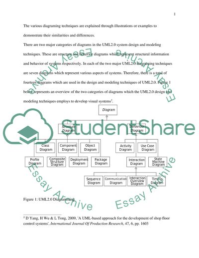
? UML2.0 DIAGRAMING TECHNIQUES of Unified Modeling Language (UML) refers to a standardized language in the design and modeling of systems which was developed by the object Management Group. In object oriented software engineering, various diagraming techniques are employed to achieve effectiveness and quality in design and modeling systems. This language is applicable in business systems which use computer software to facilitate the activities of various subsystems1. UML2.0 is a version of Unified modeling Language which is was develops to use graphic notations and modeling techniques to develop various visual models that are built and applied within systems to facilitate business activities. This paper gives a critical analysis, discussion and comparison of the various diagramming techniques and how they are used within UML2.0 to design and model systems. The various diagraming techniques are explained through illustrations or examples to demonstrate their similarities and differences. There are two major categories of diagrams in the UML2.0 system design and modeling techniques. These are structure and behavior diagrams which represent structural information and behavior of systems respectively. In each of the two major UML2.0 diagraming techniques are seven diagrams which represent various aspects of systems. Therefore, there is a total of fourteen diagrams which are used in the design and modeling techniques of UML2.0. Figure 1 below represents an overview of the two categories of diagrams which the UML2.0 design and modeling techniques employs to develop visual systems2. Figure 1: UML2.0 Diagramming All the diagrams under structural diagraming techniques of UML2.0 are similar in the fact that they all represent structural information. These diagrams are used in the design and modeling of business systems to represent the various structural components of the system such as the objects which when combined builds a system as a whole. In system modeling, structure diagrams are used to define the processes and elements of a system and the interrelationships which exist between them. Behavior diagrams on the other hand are similar in their application in system design and modeling because they are used to represent the behavior of different components of a system. However, four of the behavior diagrams are used to depict the interactions which exist among different systems. The common similarity of the UML diagrams in system design and modeling is the elements which they contain. In UML2.0 based design and modeling, the elements of a system are depicted in the diagram in defining the structure and model of the system as a whole3. The elements which are composed in the UML2.0 diagramming include actors, business activities, business processes, UML statements, database schemas, software components and logical components. Each of the elements of UML2.0 diagramming plays different roles in communicating the structure and design of the system model. In addition the diagrams within the UML.0 diagramming are basically used to visualize what the system will look like in real application after it has been constructed or installed. Through these diagrams, the required modifications to systems are explained and designed. This is because of the common feature of UML2.0 diagramming which ensures that standards are used to specify the details of design and structure of various systems. The diagrams used in UML2.0 mediated system design and modeling are aimed at ensuring the efficiency and effectiveness of systems is ascertained before they are actually built or constructed. The diagrams used in UML2.0 mediated system design and modeling are also similar in the fact that they combine different techniques in achieving the desired design and models of systems. The techniques which are employed by the UML2.0 diagraming techniques include data and business modeling. Entity relationship diagrams are specifically employed in data modeling within the UML2.0 framework of system design and modeling. In business modeling, the UML2.0 diagramming techniques employs work flows to demonstrate the directional movement of work activities within the designed systems. In addition, the UML2.0 diagraming techniques significantly employs component and object modeling to illustrate the parts or components which are contained in the designed system models. Each of the diagrams within the UML2.0 diagraming technique can be applied in the SDLC process of developing and implementing information systems. This means that the diagrams of UML2.0 mediated modeling and design is used to define and illustrate the processes involved in the development and implementation of an information system. The various notations and technologies in system development and implementation are unified by the UML2.0 diagramming techniques. This demonstrates that the UML2.0 acts as a unifying language which uses a diagramming approach and techniques to come up with a common, single or unified model of an information system. In this regard, the diagramming techniques employed by UML2.0 can be described as a common standard which acts as a guideline in the design and modeling of various business systems to ensure that consistency are maintained. Behavior diagrams depict the state machine, activities and interactions within a system. This means that these diagrams as used in UML2.0 diagraming technique are important in describing the behavior of the system in terms of the involved activities and how they interact with one another. Interaction diagrams are a subclass of the behavior diagrams which particularly emphasize on how objects within a system interact4. On the other hand, structure diagrams are different in that they are used to depict the elements of a system irrespective or regardless of the time of operation. Other features that are depicted by structure diagrams and not behavior diagrams include deployment of the system, composite structure and package diagrams. The uniqueness, functions and illustrations of each of the diagrams within the UML2.0 diagraming techniques in system design and modeling demonstrate their differences. For example class diagrams are within the structure diagrams category and are used to show static model elements which are contained in a business systems. These elements include types and classes of systems, their relationships and what each contains. Therefore many objects or classes are contained within class diagrams. The objects represent a specific conceptual or physical entity of a system while a class represents the objects which have common attributes, relationship or behavior within a group. A bank account is an example of a class diagram as illustrated in Figure 2 below. Figure 2: A Bank Account as an Example of a Class Diagram Case diagrams on the other hand are typical examples of the behavior diagram category in UML2.0 diagramming techniques. Unlike class diagrams which show the objects and classes within a system model, case diagrams are employed in representing the actors and cases of a system and the manner in which they relate. Case diagrams are one of the commonly used categories of diagrams within the UML2.0 diagramming techniques. These diagrams are used to depict and describe the behavior of a system. This includes the manner in which a system acts and its reaction while it integrates with its environment. Case diagrams have two major components. These are actors and use cases. Actors within case diagrams are parts which are used to represent the surrounding or environment within which a system exists. On the other hand, use case in case diagrams are used to represent the function which is served by the system. A good example of a case diagram is an ATM machine. This example is illustrated on Figure 3 below. Figure 3: ATM Machine as an Example of Case Diagram Component diagrams are a special category of the structure diagrams which are used in UML2.0 system and modeling to show the various components which the system is comprised of. In addition, the component diagrams can be used to depict the applications which are contained within a system or a business enterprise. In UML2.0 diagraming techniques, component diagrams are basically used to illustrate that effective system software is usually split into various small components. The component diagrams are as a result applicable in demonstrating the dependences which exist among the various system components which makes them to work as a whole in achieving the major goal or objective of a system. An order management system has various components which can be depicted through a component diagram as illustrated on Figure 4 below. Figure 3: Order Management System: Component Diagram Interaction diagrams within the UML2.0 system design and modeling approach are unique and different from other diagrams in what they depict and the functions that they represent within a system model5. Interaction diagrams are a subcategory of the behavior diagrams which are used in design and modeling to represent a specific string of system messages which are submitted and received including the relationship which exist between them. Sequence diagrams are one category of interaction diagrams which are used to design system models which are sequential and logical. These diagrams depict various classifiers and messages which exist between them to illustrate the flow of information or data within the system. A student registration system is a good example of a sequence diagram which depicts the sequence of activities and interaction of processes as illustrated on Figure 4 below. Figure 4: Student Registration System: Sequence Diagram Communication diagrams are also part of the interactive diagrams which are frequently used in UML2.0 mediated system design and modeling to depict the flow of messages within a system. In UMLL2.0 diagramming techniques, communication modeling are used to design systems for organizations which are aimed at promoting interaction, collaboration, communication and the exchange of information and data6. In design of these systems, communication diagrams are used to illustrate various instances of classes within a system and the relationship which is created between them through exchange of messages and data. The organizations or departments of a system which send and receive data are depicted within communication diagrams. A human resource management system can be used to illustrate a communication diagram as shown on Figure 5 below. Figure 5: Human Resource Management System: Communication Diagram The above illustrations demonstrate several differences among the various diagrams that are used in UML2.0 diagramming technique in the design and modeling of business systems. These differences are related to the role of these diagrams in depicting the behavior and structure of business systems. In addition, the relationships and interaction among systems is described through the use of different diagrammatic representation of models and designs that are created through application of UML2.0 diagramming techniques. For example while class diagrams are used to depict the various classes within a modeled system and their attributes, the component diagrams shows the manner in which these systems are split into minor components and their roles. In addition, the class diagrams depict the relationships which exist between classes of a system while the component diagrams illustrate the dependencies which system components have upon others. Under structure diagrams in UML2.0 design and modeling there are the composite structure diagrams which are used to describe and depict the internal organization and structure of a system class. On the other hand deployment diagrams which also fall under the structure diagram class are used to give detailed description of the various hardware components which are implemented within a specific system. Moreover, the composite structure diagrams in UML2.0 design and modeling describe the collaboration among structures of a system which makes its functionality practically applicable7. Deployment diagrams are different in applicability from the composite structure diagrams because they are basically ways through which artifacts of system hardware and the environments where these artifacts are deployed are represented. In this regard, it is apparent that regardless of falling within the same class, UML2.0 diagrams are used to depict different aspects and functionalities of the system being designed or modeled. Within the structure category of UML2.0 diagramming technique are also object diagrams and package diagrams which reveal differences in their application and what they are used to depict about the systems that are being modeled. On one hand, object diagrams are used to illustrate either a partial or complete view of the system within a specific stage of modeling. On the other hand, package diagrams are used by designers employing UML2.0 techniques to illustrate the manner in which system structure is separated into groups. The package diagrams also go further to illustrate how each of these groups depends on others. Therefore, these diagrams illustrate the whole system through a compartmentalized view of every group and its role in creating a complete system. Profile diagrams are unique among the structure diagram category which are used to stereotype various packages and classes of a system. It is in this regard that the profile diagrams are said to illustrate how systems being modeled will look at the meta-model level of design, development and implementation. In the light of the above discussion and illustrations, it is conclusive that the UML2.0 diagramming techniques provide a useful standard through which designers create models of systems before they are implemented. This is achieved through using various categories of diagrams to illustrate the various components, elements, objects and classes of systems8. More importantly, these diagrams are used to illustrate or depict the relationships, communication and coordination which exist among various aspects of a system in addition to the dependencies among components. Notably through are the similarities and difference among the various diagraming techniques of UML2.0 system design and modeling approach. The similarities among the various diagrams used in the UML.0 techniques include their elements and specific functions in illustrating different parts of a model of a system. The major differences among these diagrams emanate from the two major categorizations: structure and behavior diagrams. The subcategories under each of these major categories represent systems at different levels such as components, interaction, classes, objects, dependencies and groups. Bibliography Bendraou, R, Jezequel, J, Gervais M and Blanc, X. 2010, "A Comparison of Six UML-Based Languages for Software Process Modeling", IEEE Transactions on Software Engineering, vol. 36, no. 5, pp. 662-675. Bjorkander, M and Kobryn, C. 2008, "Architecting systems with UML 2.0", IEEE Software, vol. 20, no. 4, pp. 57-61. Nayak, A and Samanta, D, 2011, 'Synthesis of test scenarios using UML activity diagrams', Software & Systems Modeling, 10, 1, pp. 63-89 Rafe, V, Rahmani, A and Rafeh, R, 2010, 'Formal Analysis Of Uml 2.0 Activities Using Graph Transformation Systems', International Journal Of Software Engineering & Knowledge Engineering, 20, 5, pp. 679-694 Yang, D Wu, H and Tong, L. 2009, 'A UML-based approach for the development of shop floor control systems', International Journal Of Production Research, 47, 6, pp. 1601-1633 Zubcoff, J and Trujillo, J 2007, 'A UML 2.0 profile to design Association Rule mining models in the multidimensional conceptual modeling of data warehouses', Data & Knowledge Engineering, 63, 1, pp. 44-62 Read More
Cite this document
  • APA
  • MLA
  • CHICAGO
(“Compare and contrast the various diagramming techniques used in UML2.0 Essay”, n.d.)
Compare and contrast the various diagramming techniques used in UML2.0 Essay. Retrieved from https://studentshare.org/information-technology/1457560-compare-and-contrast-the-various-diagramming
(Compare and Contrast the Various Diagramming Techniques Used in UML2.0 Essay)
Compare and Contrast the Various Diagramming Techniques Used in UML2.0 Essay. https://studentshare.org/information-technology/1457560-compare-and-contrast-the-various-diagramming.
“Compare and Contrast the Various Diagramming Techniques Used in UML2.0 Essay”, n.d. https://studentshare.org/information-technology/1457560-compare-and-contrast-the-various-diagramming.
  • Cited: 0 times

CHECK THESE SAMPLES OF UML-Based Languages for Software Process Modeling

The Relationships in the Unified Modeling Language

The Unified modeling Language (UML) is a standard graphical language used for specifying, visualizing, constructing, and documenting the artifacts of software systems as well as non-software systems, and for business modeling purposes.... Being a standard language for writing software blueprints, the UML represents a collection of best engineering practices that has proven successful in the modeling of large and complex systems.... hellip; It is exclusively used to visualize, specify, construct and document the artifacts of a software-intensive system, and is appropriate for modeling systems ranging from enterprise information systems to distributed Web-based applications and even to hard real time embedded systems....
5 Pages (1250 words) Essay

Information Systems, ICT; Meta-data semantic languages, Meta Modelling REA and UMM/UML, XBRL

The receiving companies are then forced to enter relevant contents of the file manually into their system however the manual entry process is prone to error (Wang, 2007).... However, while the process proved to be faster than the conventional manual data entry, its accuracy has much to be desired.... I will go onto doing an in depth analysis of the two meta models, comparing and contrasting the two models in question and discussing why modelling is important for meta-data semantic languages....
28 Pages (7000 words) Essay

New Trends in Software Process Modeling

A comparison of six UML-Based Languages for Software Process Modeling.... The author of this essay under the title "New Trends in software process modeling" touches upon the methodology of software engineering.... New Trends in software process modeling.... The prototyping methodology aims at modeling the system that is required.... Reflections on the modularity of business process models: The case for introducing the aspect-oriented paradigm....
2 Pages (500 words) Essay

Software Engineering and Human Computer Interaction

The paper “Software Engineering and Human-Computer Interaction” seeks to evaluate human-computer interaction which refers to employing computers and other technical systems in, for example, the process industry, or at home where video recorders and other gadgets are becoming part of our everyday lives.... he answer is that, if we don't consider HCI, we will almost certainly run into problems at the end of the development process.... One more important factor is user involvement in the software development process, for example by applying a user-centered approach called User-centred design or UCD....
10 Pages (2500 words) Dissertation

Comparing the Use of the IDEF Methodology to UML

This comparison will be done on the basis of credible and reliable literature, written and published by authorities on modeling languages and techniques.... he approach/rationale for UML is to act as the dominant, publicly accepted, and uniform objected-oriented visual modeling language, and as a foundation object description language for the offshoot unified enterprise modeling language (UEML) that has been put forward by IFAC/IFIP (Bernus, Mertins, & Schmidt 1998, pg....
6 Pages (1500 words) Essay

Unified Modelling Language as a Modelling Technology

The concept of collaborative learning refers to a team learning process where members of the team support each other to reach an agreed target.... The UML is a modelling tool that is used to specify, visualize, modify, construct and document the artefacts of an object-oriented software-intensive system under development (FOLDOC, 2001).... The major components of UML include actors, business processes, activities, states, reusable software components etc (Booch et al....
8 Pages (2000 words) Research Proposal

Unified Software Development Process and Object-Oriented Analysis and Design

of unification modeling language (UML).... was adopted as the standard OOAD modeling language.... The paper "Unified Software Development process and Object-Oriented Analysis and Design" outlines that the amalgamation of OOAD, with the development of Object-Oriented software, which results in a consistent process that produces excellent software in a predictable and fast manner.... MotivationThe chief motivation for this venture is to establish opportunities, as well as challenges associated with applying the process of unified software development, with the technology of Object-Oriented....
6 Pages (1500 words) Literature review

Unified Software Development Process and OOAD

OOA employs object-modeling techniques during a system analysis phase.... With the Rational Unified process in mind, research on how best UML (Unified modeling Language) can be implemented in the software development process to produce better applications.... Some experienced companies came up with six best approaches to software engineering and these approaches were Iterative development (with risk possible of primary iteration), requirement management, implementation of component-based architecture, visually modeling of software products, progressive (continuously) quality verification and control changes....
9 Pages (2250 words) Report
sponsored ads
We use cookies to create the best experience for you. Keep on browsing if you are OK with that, or find out how to manage cookies.
Contact Us