StudentShare
Contact Us
Sign In / Sign Up for FREE
Search
Go to advanced search...
Free

Chemical Safety: Relief Valves - Coursework Example

Cite this document
Summary
"Chemical Safety: Relief Valves" paper states that a relief valve can bypass the fluid anytime and all the time without the requirement of maintenance to restart the system. Another implication is that the system is able to run hot even if there’s no heat exchanger installed…
Download full paper File format: .doc, available for editing
GRAB THE BEST PAPER98.4% of users find it useful
Chemical Safety: Relief Valves
Read Text Preview

Extract of sample "Chemical Safety: Relief Valves"

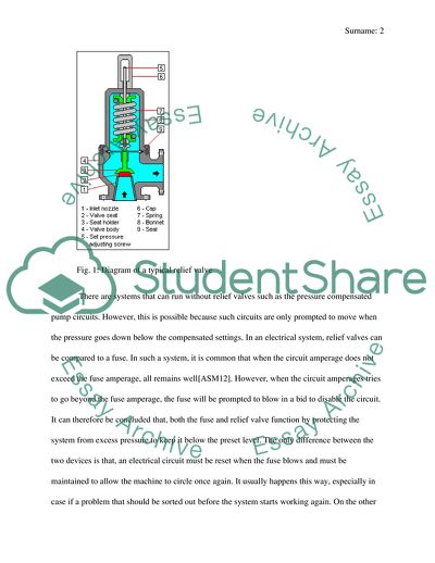
Chemical Safety Chemical Safety: Relief Valves In Chemical safety, relief valves are described as safety device of the system that becomes useful in protecting and preventing the vessels and systems from operating beyond the allowable or set safe limits. All the circuits with fixed volumes usually need a relief valve for the system protection against excess pressure. The fixed-volume pumps are meant to move fluids whenever they are turning. There’s no problem with the fluid movement especially when either pumps unload through an open-center circuit or the actuators are in a movement. A relief valve becomes essential when the actuators stall with thee directional valve in a still shifted position. Fig. 1: Diagram of a typical relief valve There are systems that can run without relief valves such as the pressure compensated pump circuits. However, this is possible because such circuits are only prompted to move when the pressure goes down below the compensated settings. In an electrical system, relief valves can be compared to a fuse. In such a system, it is common that when the circuit amperage does not exceed the fuse amperage, all remains well (ASME 61). However, when the circuit amperages tries to go beyond the fuse amperage, the fuse will be prompted to blow in a bid to disable the circuit. It can therefore be concluded that, both the fuse and relief valve function by protecting the system from excess pressure to keep it below the preset level. The only difference between the two devices is that, an electrical circuit must be reset when the fuse blows and must be maintained to allow the machine to circle once again. It usually happens this way, especially in case if a problem that should be sorted out before the system starts working again. On the other hand, relief valves in the hydraulic system, opens and bypass the fluid whenever the pressure goes beyond the preset level. After the pressure falls, the valve will automatically close gain. In essence, it shows that a relief valve can bypass the fluid anytime and all the time without the requirement of maintenance to restart the system. Another implication is that, the system is able to run hot even if there’s no heat exchanger installed. It is important for many fixed-volume pump circuits t have the bypassing capability of the relief valve during the circle as some also a have the bypassing during the idle time according to design, it is common that when a circuit is designed well, it does not bypass a fluid unless in the case of a malfunction. Some malfunctions common in the circuit include the operator overriding the controls or cases where the limit switch is not closing. When a bypass takes place during such malfunctions, there’s a possibility of eliminating overheating problems that go ahead to save energy. How Relief Valves Operate As has been discussed above, relief valves are automatically prompted to operate when the pressure in the system exceeds the pressure set in the valve and causes a force to be exerted on the valve disc that then act by overcoming the spring force that is opposing from the internal part. According to their codes, valves are able to open with a given range of tolerance which can be within +/-3% range of the stamped and set pressure (ASME 61). At this rate, a full capacity is usually realized at 10% above the real opening pressure. When selecting relief valves, more attention should be focused on the discharge capacity that is needed for either the vessel or the system. This can also be based on the equipment size as well as the refrigerant in use. The valves should be set at a minimum of at least 25% above the maximum designed operating pressure. When the location of the valve is expected to experience ambient temperatures, especially on the roofs or the rooftops, there should be an additional special consideration given to the relief valve. It is usually helpful to size the valves to the maximum allowable setting so as to minimize the seepage possibility or early discharge. In as much as valves are usually designed to reseat automatically after discharge, it is advisable to replace them. This is important because it is determined that there are a lot of system impurities such as solder, piping debris and metal shavings that have a high likelihood of accumulating under the valve disc and cause inhibition of the proper valve sealing. Design and Design Considerations Two main different designs of relief valves are available in use. These designs are mainly the direct acting and pilot operated relief valves. Both the designs have their own advantages and areas of applications where they work better. Direct-acting Relief Valve Fig. 2: Cutaway drawing and symbol for direct acting relief valve. The poppet on the valve is pressed by the adjustable spring against its seat. The valve is also fitted with an adjustable knob that is capable of changing the spring force so as to lower or raise the maximum pressure. The moment the pump flow goes to the circuit, the poppet remains seated, and at this moment, the pressure is lower than the relief valve setting. It is the poppet that is usually forced of the seat the moment the pressure tries to go above the spring setting to allow the excess pump flow to the tank. The symbol has a single box with an arrow showing the flow that offsets from the inlet indicated with letter P and the outlet shown with letter T (Trinke 3). the inlet pressure is shown to be able to push against the flow arrow by the dashed pilot line starting from the inlet line down to the bottom of the box. There’s a spring with a sloping arrow through it, right on the opposite side of the box, that shows the opposing force on the flow arrow. There is a time when the pressure at the port P builds up to overcome the pressure of the spring, and this forces the flow arrow to come up until a path is created from P to T. Even if a pilot passage is not shown in te actual valve, its function is implied that makes it part of the symbol. Pilot-Operated Relief Valves Fig. 3: Cutaway views and symbol for two common types of pilot-operated relief valves In as much as various variations in design are available for the pilot-operated relief valves, its symbol and function is just the same. In the poppet, also known as the balanced piston, there is a control orifice with a diameter of around 0.040 in. this size is recommended as it provides a good stability for relief-flow and it is not easily locked with contamination. The poppet or balanced piston is expected to open at an estimated 20 psi when the orifice is plugged so that it can dump all the pump flow into the tank. On top of the poppet or the balanced piton, there is a flow path emerging from the outlet of the control orifice and moves on to the pilot section having a spring loaded poppet. When the tension on the spring loaded poppet is adjusted the pressure in the circuit is set. The fluid that has been used by the pilot section is directed to return to the tank through the port on the tank. There’s also a hole through the balanced piston that allow the control fluid to flow easily to the tank. There is also a vent port in the plot section which is usually plugged (Trinke 7). When the plugged is removed, the valve can be able to perform other functions. For piping convenience, many inline-mounted valves are usually fitted with two inlet port. In this case, the pump flow is directed to flow in one of the inlet and makes an exit through the one on the opposite side. Materials Relief valves are made carbon steel or stainless steel with Teflon or any other type of plastic seats. The valve are usually balanced against backpressure without the need for bellows and they are usually considered to be charter free. The valves are made to comply with the ASME Section VIII or “CE” mark, ASTM or JIS. Cast steel or forged steel can also be used as a body material for the relief valves. Carbon steel, 1 Cr0.5Mo steel and 2.5CR1Mo steel are also good for the body materials. Such a valve is usually used with water as the min fluid (Okano 2). Vendors and Pricing The Relief valves are manufactured and distributed by various fluid power companies all over the world. Its prices are also different depending on the country, company manufacturing conditions and quality, sizes and various other differences in design. In the United States, for example, there are very many manufacturers and distributors one of them being Fulflo Manufacturers. The valves from Fulflo range from 3/8”-4’’ and works with such liquids of any viscosity starting from 2-1000 psi. The company also does its pricing differently depending on the series of the valve. Among the series available, there are V-series valves, FV-series, OV-series, A-series and SVB-series among others. The prices generally range from $90-150 per piece (Fulflo 12). Limitations of the Relief Valves The limitations of relief valve are more specified when each type of relief valve is considered. For instance, weighted pallet relief valves have various limitations including the fact that it is not easy to adjust its set pressure, it has extremely long simmer and poor tightness and it requires high overpressure for full lift (Pentair 2). The conventional metal seated valves have limitations such as vulnerability to the effects of inlet pressure losses, it is not easy to obtain accurate in-place pressures set for verification and it is sensitive to the effects of back pressure. The other relief valve type is balanced bellows or the metal seated with limitations such as having it maintenance costs being high, the bellows having life limitations, vulnerability to the effects of losses in inlet pressure and the inability to maintain accurate set in-place pressure verifications. Sizes for Various Application Purposes A standard relief valve for industrial application is made of an area of 4.34 square inches as the smallest standard size to flow the required relieving capacity (Whitesides 9). A pilot application valve can also be selected for industrial application since its performance is not affected by back pressure. For selection purposes, the following tale can be used with various set pressures to select the various valve capacities in pounds per hour saturated steam plus 10% over pressure. Set Pressure (psi) ORIFICE DESTINATION D E F G H 10 141 252 395 646 1009 20 202 360 583 923 1410 30 262 467 732 1200 1872 40 323 575 901 1476 2304 50 383 683 1070 1753 2736 Works Cited ASME. "Pressure Relief Valves." ASME Publication (2012): 61-71. Print. Fulflo. "Hydraulic Bypass Relief Valves." Fulflo Specialties Company (2013): 1-52. Print. Okano. "Safety Valve / Relief Valve." Okano Valve Manufacturing (2011): 1-3. Web. Pentair. "Valves and Controls: Advantages and Limitationsof Valve Types." Pentair (2013): 1-5. Web. Trinke, Bud. "Relief and Unloaading Pressure Controls." Hydraulics and Pneumatics (2007): 1-23. Web. . Whitesides, Randal. "Selection and Sizing of Pressure Relief Valves." PHD Center (2012): 9-22. Print. Read More
Tags
Cite this document
  • APA
  • MLA
  • CHICAGO
(Chemical Safety: Relief Valves Coursework Example | Topics and Well Written Essays - 1750 words, n.d.)
Chemical Safety: Relief Valves Coursework Example | Topics and Well Written Essays - 1750 words. https://studentshare.org/engineering-and-construction/1881593-chemiacl-saftey
(Chemical Safety: Relief Valves Coursework Example | Topics and Well Written Essays - 1750 Words)
Chemical Safety: Relief Valves Coursework Example | Topics and Well Written Essays - 1750 Words. https://studentshare.org/engineering-and-construction/1881593-chemiacl-saftey.
“Chemical Safety: Relief Valves Coursework Example | Topics and Well Written Essays - 1750 Words”. https://studentshare.org/engineering-and-construction/1881593-chemiacl-saftey.
  • Cited: 0 times

CHECK THESE SAMPLES OF Chemical Safety: Relief Valves

Citizen Involvement With the Law Enforcement Agency

Citizen Involvement with their Law Enforcement Agency Name of the Student Law Name of the Concerned Professor March 5, 2013 Abstract In the current times, community participation is often considered to be a panacea for all socio-political problems and issues.... hellip; There is no denying the fact that when the institutions and especially the law enforcement bodies and organizations tend to fail in the carrying out of their responsibilities or do not have the man power and the resources to leverage their efficiency and reach, citizen involvement could indeed turn out to be a viable leverage and a potential force multiplier....
6 Pages (1500 words) Essay

Analyse the impact of effective training on a company. Support your answer with examples

Training equips them with knowledge on safety, skills, values, problem-solving, and hazard awareness.... ANALYZING THE IMPACT OF EFFECTIVE TRAINING ON A COMPANY.... Instructor Institution Location Date Introduction Training is a system of developing of an individual's skill behaviour pattern and attitude with the objective of enabling them to perform given tasks adequately....
4 Pages (1000 words) Essay

Printing and Advertising Services

The ad will then have reminded them that road safety is paramount and is the collective responsibility of not just law enforcers, but the passenger's as well.... This essay presents printing and advertising services which are gaining utmost significance in the way they are able to influence people through the messages they pass....
4 Pages (1000 words) Essay

Changes in Apple's Supplier Code of Conduct

That is why at Apple, we really care about the safety and health of our workers.... In an effort to assure that safety and good health is maintained, we launched about 870 projects in 2014 to improve conditions at the places of work.... This was done through the Environment, Health, and safety (EHS) Academy.... We have also come up with a comprehensive mapping program that aims to make steadfast our chemical management functions....
4 Pages (1000 words) Essay

Developing a Strategic Plan for a Company

(Michael 2005)  The services and support which are in the processing of expanding include planned relief residential support, job support and replacement, social activities, and respite care.... The underlying purpose of this discussion "Developing a Strategic Plan for a Company" is to examine strategic planning as the whole planning that will facilitate good and efficient management of an organization or project....
5 Pages (1250 words) Case Study
sponsored ads
We use cookies to create the best experience for you. Keep on browsing if you are OK with that, or find out how to manage cookies.
Contact Us