StudentShare
Contact Us
Sign In / Sign Up for FREE
Search
Go to advanced search...
Free

Main Hydraulic Pump Motor and Starter Systems - Assignment Example

Cite this document
Summary
This research is being carried out to evaluate and present main hydraulic pump motor and starter systems. The paper tells that the earlier devices were never operated with hydraulic systems, but they were powered by air, electricity, or both…
Download full paper File format: .doc, available for editing
GRAB THE BEST PAPER98.6% of users find it useful
Main Hydraulic Pump Motor and Starter Systems
Read Text Preview

Extract of sample "Main Hydraulic Pump Motor and Starter Systems"

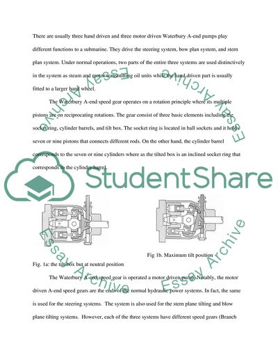
Main Hydraulic Pump Motor and Starter Systems Since the prewar era, submarine has experienced developmental improvements. Among the improvements is the size that have since changed from smaller and simple submarine devices to large and complex devices that are currently operated by hydraulic power systems (Branch 86). Notably, the earlier devices were never operated with hydraulic systems, but they were powered with air, electricity, or both. The hydraulic powers systems that are currently used in the submarine systems and devices are not only used in powering the devices but also used in operating other systems within the vessels. The submarines also require the use of electric power especially for propulsion as well as operating auxiliary equipment within the vessel. Other than moving stationary light equipment, electricity is often used in instantaneous stopping some equipment such as electric motors (Branch 55). Motors often have the tendency to drift and/or over-travel thereby becoming difficult to control without electricity. Additionally, electric driven equipment are often noisy and require intense maintenance; therefore, to overcome these shortcomings, the submarine devices are currently designed and manufactured to use hydraulic powering systems including hydraulic motor pumps. Hydraulic motors are the power units of the marine devices; however, they do not generated their own power, but they often convert hydraulic power into mechanical energy that is transmitted to other parts of the vessel. Therefore, pumps are the central power supply for the devices using hydraulic systems. The pumps are used to create pressure within the system. Submarine devices usually have different pumps playing different roles (Branch 98). The Waterbury A-end pump is among the pumps using in the submarine devices. A rotating shaft operates the Waterbury A-end pump. The rotating shaft may be operated by hand or motor. There are usually three hand driven and three motor driven Waterbury A-end pumps play different functions to a submarine. They drive the steering system, bow plan system, and stern plan system. Under normal operations, two parts of the entire three systems are used distinctively in the system as steam and motor transmitting oil units while the hand driven part is usually fitted to a larger hand wheel. The Waterbury A-end speed gear operates on a rotation principle where its multiple pistons are on reciprocating rotations. The gear consist of three basic elements including the socket ring, cylinder barrels, and tilt box. The socket ring is located in ball sockets and it holds seven or nine pistons that connects different rods. On the other hand, the cylinder barrel corresponds to the seven or nine cylinders where as the tilted box is an inclined socket ring that corresponds to the cylinder barrel. Fig. 1a: the tilt-box but at neutral position Fig 1b. Maximum tilt position The Waterbury A-end speed gear is operated a motor driven pump. Notably, the motor driven A-end speed gears are the ends of the normal hydraulic power systems. In fact, the same is used for the steering systems. The system is also used for the stern plane tilting and blow plane tilting systems. However, each of the three systems have different speed gears (Branch 120). For instance, the motor for the steering system drives the speed gears at the rate of 15 horsepower per minute this speed is higher than that of speed gears for the bow and stern plane tilting systems, which is at 7.1 horsepower per minute for each. The Waterbury A-end pumps also employ the three motor and hand driven hydraulic systems that also control submarine steering system as well as bow and stern plane tilting systems. The enables coupling of the normal powers with hydraulically generated power. The submarine vessels also use the Waterbury B-end speed gears. These gears also uses the hydraulic systems as their primary pumping mechanisms. These gears use hydraulic motors to covert hydraulic fluid to mechanical torque. The B – end Waterbury are usually in two forms the 10-B motor used in the latest class of the submarine vessels that are designed by Portsmouth and Electric Boat Company. The hydraulic power of these 10 –B vessels are usually installed on the main hydraulic system (Branch 133). The system usually carry a series of gear trains that operates forward capstan, bow plane rigging gear, and anchor windlass. The main hydraulic systems of the submarine devices require immense and professionalized maintenance services for them to work effective and for longer periods. Notably, the submarine devices and vessels’ components are highly automated; therefore, they currently require highly qualified ETO to operate and maintain them (Branch 149). Additionally, they require ETOs who are highly learned of the structures and systems components of these systems. Otherwise, poor understanding will only lead to poor operations and maintenance services thereby leading to their untimely degradation and dis-function. The advancement in technology has brought a great impact to the managing and maintenance of many oil tankers systems (Branch 152). This has been accelerated by the automation of most systems in the ship, which has led to easy management and monitoring. It is the function of the ETO to perform mechanical, Electronic, and hydraulic system checks towards identifying failures and correcting the same. The starboard main hydraulic pump motor and starter system are some of the crucial systems in an oil tanker. The movement and control of the oil tanker as like other submarine vessels are controlled through hydraulic systems. The starter system starts and stops the power transmission throughout the vessels; hence, it forms a vital component of the vessel that also require maintenance towards effective functionality. Starboard Main Hydraulic Pump Motor has a very significant role in the engine control and maneuvering systems of the oil tanker. Before a ship docks, the ETO should perform a thorough check up of all its components (Branch 165). This will reduce the risks associated with systems failure including the failure of the hydraulic pump motor. These maintenance services usually follow a manual that is provided for by the manufacture towards any form of maintenance services. Figure 2: Starboard Main Hydraulic Pump Motor The main hydraulic pumping motor system is made up of several units of pumps and motors that function distinctively but with collective input to the effective operation and functionality of the submarine vessel. Below is a drawing showing the main hydraulic pumping system of a submarine vessel. Fig 4: the sematic diagram showing power generation and transmission with the main hydraulic system 1. IMO pumps 2. 18 horsepower motors 3. Non return valves and automatic bypass valves 4. Accumulator 5. Pilot valves 6. The main supply tank 7. The main supply manifold 8. The main return manifold 9. The air flask accumulator 10. Back pressure air, tank, or volume 11. The non-return valves 12. The air loaded relief valve 13. It should be noted that the despite the different and simple hydraulic units of the main hydraulic system, the effective functionality of individual unit is very vital and necessary. Therefore, the maintenance services should target individual unit towards the whole. Some of the elements that must be checked and eradicated are those that will interfere with efficiency of the machine. The presence of the air in the systems is likely to affect the efficiency and functionality of the hydraulic systems; therefore, air must be prevented at all costs from system (Branch 178). Nonetheless, there should be frequent hydraulic system check to ensure that air does accumulate in any case it find its way into the system. This maintenance principle and requirement also applies in the maintenance of the Waterbury speed gears that must remain filled with oil all through as well as being free of oil bubbles. Venting off any accumulated air involves opening vent valves of the top valve plates. 14. 15. Fig 3: Valve Plate Cutaway 1. Main shaft bearing 2. Collector channel 3. Air vent 4. Replenishing valve 5. Replenishing valve retainer plug 6. Port 16. 17. 18. 19. 20. 21. 22. The shaft is turned few times with open vent valves to ensure that air is expelled completely. Despite this precaution, some air may remain trapped into the Waterbury gear; therefore, to ensure that air is flashed out completely, the Waterbury gears are set running without load but with closed valves for a few minutes after which the valves are opened until air is removed completely. Notably, this procedure should be conducted periodically until all air is removed from the main hydraulic system. In most cases, the presence of air within the hydraulic system is often detected by noisy and/or speedy vibration in the B-end Waterbury hydraulic gears thereby slowing down the under loads. 23. Another aspect of maintenance of the hydraulic motors is through proper or couscous handling of the Waterbury speed gears. This includes evading unnecessary sustained overloads and never allowing A- end to remain operational unnecessarily (Branch 192). The main hydraulic system of submarine systems should never be opened for inspection when they are operating satisfactorily. Notably, these units usually give best service when intact and not disturbed. Therefore, if any service calls for overhaul, the Waterbury speed gears should be assembled carefully and attended only by specialized engineers and tools. The main hydraulic system of the submarine device usually perform the bulk of these vessels’ hydraulic work and their operations usually starts from the hand since all manifold controls are through hand levers that are place in a hand position. 24. Individual unit of the hydraulic system often performs the tilting and steering operations; therefore, to provide assurance against any system failure, it would be vital to use the main hydraulic system’s pressure to power the gears o enable articulation of planes and rudder. Therefore, from such energy transmission system, groups of valve within the steering and plane system will provide for required power to handle any sort of emergency (Branch 201). Therefore, there are needs for these units to be sound in their functions. In other words, it is the function of main hydraulic system to provide hydraulic power to handle emergencies. All these are handled through the steering system in the control room or from conning tower. 25. 26. Fig 5: steering system schematic view 27. 28. Fig 6a: steering manifold of the main hydraulic system; top view 29. 30. Fig 6b: steering manifold of the main hydraulic system; top vie 31. 32. 33. 34. 35. Fig 7: control room steering stand 36. Figure 8: Hydraulic Pump Motor and Starter System 37. 38. Figure 9: Circuit Diagram for the Hydraulic Pump Motor and Starter System 39. The Hydraulic Pump and Starter Systems are vital component of submarine vessels. The starter system starts the operation of the vessel for different components while hydraulic systems control the main operations of the vessels including movement and stoppage. Therefore, it is vital that persons who have their full understanding these systems should operate them to reduce unintended damages that might lead to system failures. The system failures are only not economic to the operation and use of these vessels; they are also dangerous to the lives within the vessel among other lives. 40. 41. Work Cited 42. Top of Form 43. Branch, Alan E. Economics of Shipping Practice and Management. London: Chapman and Hall, 1982. Internet resource. 44. Bottom of Form 45. Read More
Cite this document
  • APA
  • MLA
  • CHICAGO
(“Main Hydraulic Pump Motor and Starter Systems Assignment - 3”, n.d.)
Main Hydraulic Pump Motor and Starter Systems Assignment - 3. Retrieved from https://studentshare.org/engineering-and-construction/1687734-electro-mcnichael
(Main Hydraulic Pump Motor and Starter Systems Assignment - 3)
Main Hydraulic Pump Motor and Starter Systems Assignment - 3. https://studentshare.org/engineering-and-construction/1687734-electro-mcnichael.
“Main Hydraulic Pump Motor and Starter Systems Assignment - 3”, n.d. https://studentshare.org/engineering-and-construction/1687734-electro-mcnichael.
  • Cited: 2 times

CHECK THESE SAMPLES OF Main Hydraulic Pump Motor and Starter Systems

Aircraft Electrical Power Generation and Distribution

This charge pressure is made by a charge pump and charge relief valve; the charge oil is also used to cool the generator.... Drain oil from the generator and sump is supplied through a scavenge filter to an external oil cooler by three pumps , which are driven by the accessory drive gear on the differential gear These pumps are generator scavenge pump, sump scavenge and inversion scavenge pump.... The accessory drive gear also drives the de-aerator and charge pump....
8 Pages (2000 words) Coursework

Logistics - ELME MicroMotion System

This essay "Logistics" compares the container handling equipment requirements of a container terminal used for high-density throughput and a container terminal that is associated with a multipurpose role.... Historically dependable container handling solutions make ELME a principal force in container terminals....
9 Pages (2250 words) Essay

The Design and History of Lockheed C-130 Hercules Aircraft

The flexible and multipurpose C-130 aircraft can accommodate a number of different sized cargo including military equipment, six wheeled vehicles, air force helicopters.... The design is made such that it should be able to serve a number of purposes.... To make it dual purpose the fitting of equipment is such that they are easily detachable....
9 Pages (2250 words) Essay

Aircraft Fuel System

This paper ''Aircraft Fuel System'' tells that The two types of electronic engine management systems found on modern aircraft are the Full Authority Digital Electronic control system and the hydro mechanically control scheme.... The two switches are the source of energy to the aircraft systems.... There are additional cockpit controls and switches to control the fuel pump with FADEC power supply, protecting them (BTEC Unit 81 handout)....
12 Pages (3000 words) Report

Micro Hydropower Plant

A rotor motion is generated by a starter unit until a required design speed is generated which is enough to maintain the whole unit running.... "Micro Hydropower Plant" paper focuses on the fundamental principles of steam that play an important role in the operation of the power plants....
17 Pages (4250 words) Coursework

Compressor and Pump

The simple types of compressors are the ones used to inflate air into tires of motor vehicles and bicycles.... … The paper "Definition of Compressor and pump" is a good example of a term paper on engineering and construction.... The paper "Definition of Compressor and pump" is a good example of a term paper on engineering and construction.... This is also the main element and mechanism that is used by all the compressors....
16 Pages (4000 words) Term Paper

Artificial Lift Technologies and Their Relevance in Production Optimization

The "Artificial Lift Technologies and Their Relevance in Production Optimization" paper elucidate the advantages and disadvantages of artificial lift technologies and their relevance in production optimization.... The utilization of SPE focuses on the make-to-order mode of the manufacturing model....
10 Pages (2500 words) Term Paper

Modelling and Optimal Control of Tower Crane Motions

This case study "Modelling and Optimal Control of Tower Crane Motions" presents the market rate and the product that will be delivered within a period of 21 days without delay.... We have delivered similar products to various organizations.... We undertake full responsibility for the failure of the item....
11 Pages (2750 words) Case Study
sponsored ads
We use cookies to create the best experience for you. Keep on browsing if you are OK with that, or find out how to manage cookies.
Contact Us