StudentShare
Contact Us
Sign In / Sign Up for FREE
Search
Go to advanced search...
Free

Heat and mass transfer calculation for carbon capture pilot plant - Assignment Example

Cite this document
Summary
The first is that holding the mass flow rate and temperature of the hot stream steady and increasing the flow of the cold stream led to a steady improvement of the thermal efficiency of the apparatus. This supports the theory…
Download full paper File format: .doc, available for editing
GRAB THE BEST PAPER95.3% of users find it useful
Heat and mass transfer calculation for carbon capture pilot plant
Read Text Preview

Extract of sample "Heat and mass transfer calculation for carbon capture pilot plant"

Heat transfer aspects Experiment Temperature reduction for the Hot Fluid ∆t Hot = T1 – T2 = 57.5 – 53.2 = 4.3KTemperature increase for the Cold Fluid ∆t Cold = T4 – T3 = 25.4 – 13.2 = 12.2KTable below shows the summary of the observations and calculations Obs. No.Vhot(g/s)Vcold(g/s)T1°CT2°CT3°CT4°C∆t Hot (T1-T2) K∆t Cold (T4-T3) K1501557.553.213.225.44.312.22502057.252.713.323.34.5103502756.952.413.120.84.57.74503156.751.413.321.55.38.2Experiment 2Mean Temperature = (T1 + T2)/2 = (57.5 + 53.2)/2 = 55.

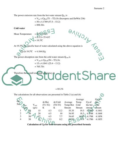
350CCp of Water at Temperature T equals6x10-9 T4 – 1x10⁻⁶ T3 + 7.0487x10⁻⁵T2 – 2.4403x10⁻³ T +4.2113Cp at 55.350C = 4.1789J/gThe power emission rate from the hot water stream Qhot is = Vhot x Cphot(T1 – T2) J/s (Incropera and DeWitt 236) = 50 x 4.1789 (57.5 – 53.2) = 898.5J/sCold waterMean Temperature = (T3 + T4)/2 = (13.2+ 25.4)/2 = 19.30CAt 19.30C the specific heat of water calculated using the above equation is Cp at 19.30C = 4.1841J/gThe power absorption rate from the cold water stream Qcold is = Vcold x Cpcold(T4 – T3) J/s = 15 x 4.1841 (25.4 – 13.2) = 765.

7J/sTherefore the overall exchange efficiency ƞ = 85.2%The calculations for all observations are presented in Table-2 (a) and (b)Ob. No.Vhot (g/s)Vcold (g/s)∆t Hot (T1-T2) K∆t Cold (T4-T3) KAverage Temp Hot StreamAverage Temp Cold StreamCp of the hot streamCp of the cold stream150154.312.255.3519.34.17894.1841250204.51054.9518.34.17884.1848350274.57.754.6516.954.17884.1858450315.38.254.0517.44.17864.1855Calculation of Cp for both streams using the prescribed formulaObs. No.Heat loss rate for hot streamHeat gain rate for cold streamThermal Efficiency1898.5765.785.2%2940.2837.089.0%3940.2870.292.6%41107.31063.996.1%Calculation of Thermal EfficienciesWe observe two important things from our findings.

The first is that holding the mass flow rate and temperature of the hot stream steady and increasing the flow of the cold stream led to a steady improvement of the thermal efficiency of the apparatus. This supports the theory that increased flow creates more turbulence and improvement in the heat transfer coefficient. The second observation is that the improvement of efficiency might also have resulted in a gradual reduction of heat losses from the system as the experiments were performed one after the other and despite the fact that sufficient time was allowed for the system to become stable.

Experiment 3A sample of the calculations is as follows:Temperature reduction for the Hot Fluid ∆t Hot = T1 – T2 = 56.4 – 48.3 = 8.1KTemperature increase for the Cold Fluid ∆t Cold = T4 – T3 = 42.9 – 21.3 = 21.6Kthe summary of the observations and calculationsObs. No.Vhot(g/s)Vcold(g/s)T1°CT2°CT3°CT4°C∆t Hot (T1-T2) (K)∆t Cold (T4-T3) (K)1401456.448.321.342.98.121.62342055.543.421.340.712.119.43282656.440.421.137.416.016.34223256.835.821.234.921.013.7The calculations show that with increase in the flow rate of both streams the temperature drop of the hot stream increased steadily.

On the other hand, the temperature rise of the cold stream decreased substantially. The clear jacket allowed the observation that the jacket was continuously full at all times and because neither stream had any color, it was not possible to notice whether the turbulence of the two streams changed at all. In future experiments it might be a good idea to introduce a small stream of dye into both streams to observe turbulence. However, this would lead to a change in the mass flow rate and more importantly in the specific heat capacity, which would have to be accounted for in subsequent calculations.

Experiment 4Mean Temperature = (T1 + T2)/2 = (56.4 + 48.3)/2 = 52.350CCp of Water at Temperature T equals6x10-9 T4 – 1x10⁻⁶ T3 + 7.0487x10⁻⁵T2 – 2.4403x10⁻³ T +4.2113Cp at 52.350C = 4.1783J/gThe power emission rate from the hot water stream Qhot is = Vhot x Cphot(T1 – T2) J/s = 40 x 4.1783 (56.4 – 48.3) = 1353.8J/sCold StreamMean Temperature = (T3 + T4)/2 = (21.3+ 42.9)/2 = 21.60CAt 21.60C the specific heat of water calculated using the above equation is Cp at 21.60C = 4.

1783J/gThe power absorption rate from the cold water stream Qcold is = Vcold x Cpcold(T4 – T3) J/s = 14 x 4.1783 (42.9 – 21.3) = 1263.7J/sTherefore the overall thermal efficiency ƞ = 93.3%The calculations for all observations are presented in Table-4 (a) and (b)Obs. No.Vhot (g/s)Vcold (g/s)∆t Hot (T1-T2) (K)∆t Cold (T4-T3) (K)Average Temp Hot StreamAverage Temp Cold StreamCp of the hot streamCp of the cold stream140148.121.652.3532.14.17834.17892342012.119.449.45314.17794.

17913282616.016.348.429.254.17794.17964223221.013.746.328.054.17774.1800Calculation of Cp for both streams using the prescribed formulaObs. No.Heat loss rate for hot streamHeat gain rate for cold streamThermal Efficiency11353.81263.793.3%21718.81621.594.3%31871.71771.394.6%41930.11832.594.9%Important findings of this experiment are that the thermal efficiency of the plate and frame heat exchanger is better than that of the concentric tube heat exchanger and secondly, with the increase in flow rate the efficiency improved only marginally.

This is perhaps because with the multiple pass arrangement where the two streams changed direction frequently an element of turbulence was already present that did not change much with the change in flow rates. However, the observations taken are too few to arrive at this conclusion with confidence. Experiment 5Mean Temperature = (T1 + T2)/2 = (57.9 + 53.6)/2 = 55.750CCp of Water at Temperature T equals6x10-9 T4 – 1x10⁻⁶ T3 + 7.0487x10⁻⁵T2 – 2.4403x10⁻³ T +4.2113Cp at 55.750C = 4.1790J/gThe power emission rate from the hot water stream Qhot is = Vhot x Cphot(T1 – T2) J/s = 50 x 4.1790 (57.9 – 53.6) = 898.

5J/sCold StreamMean Temperature = (T3 + T4)/2 = (14.2+ 25.5)/2 = 19.850CAt 19.850C the specific heat of water calculated using the above equation is Cp at 19.850C = 4.1837J/gThe power absorption rate from the cold water stream Qcold is = Vcold x Cpcold(T4 – T3) J/s = 16 x 4.1837 (25.5 – 14.2) = 756.4J/sTherefore the overall thermal efficiency ƞ (Dincer and Konoglu 136) = 84.2%The calculations for all observations are presented in Tables below Calculation of Cp Obs. No.Vhot (g/s)Vcold (g/s)∆t Hot (T1-T2) (K)∆t Cold (T4-T3) (K)Average Temp Hot StreamAverage Temp Cold StreamCp of the hot streamCp of the cold stream150164.311.355.7519.854.17904.1837250204.610.155.519.154.17904.1842350264.98.355.3518.054.17894.1850450345.26.85516.904.17884.

1859Calculation of exchange EfficienciesObs. No.Heat loss rate for hot streamHeat gain rate for cold streamThermal Efficiency1898.5756.484.2%2961.2845.287.9%31023.8903.188.2%41086.5967.889.1%Calculation of exchange EfficienciesImportant findings of this experiment are that the thermal efficiency of the plate and frame heat exchanger is comparable to that of the concentric tube heat exchanger but lower than that of the plate and frame heat exchanger. Secondly, with the increase in flow rate of the cold stream the efficiency improved marginally.

In this case again, the conclusion can be that the design allows for introducing greater turbulence in the shell-side stream through the baffles provided.Mass transfer aspects Mass transfer is calculated as shown below; Mass transfer = Overall mass transfer coefficient x Actual driving force mol/m3 Overall mass transfer coefficient= (Kreith, Manglik and Bohn 175)KG Mass transfer coefficient in the gas phase m/sKL Mass transfer coefficient in the liquid phase m/sKov Overall mass transfer coefficient m/sm Solubility of carbon dioxide at equilibriumE = = 1.

011Ha = = 0.382Ha -Hatta modulesD CO2 ,am - CO2 diffusivity in the MEA solution m2/sk2 Forward second order reaction rate constant m3/mol.sCMEA - MEA concentration mol/m3E Enhancement factorE = = 57.25 Overall mass transfer coefficient= = 0.716Mass transfer = 0.716 x 0.278 = 0.1991Works Cited Incropera, Frank and David, DeWitt. Fundamentals of Heat and Mass Transfer. New York: John Wiley & Sons, 2002. PrintDincer, Ibrahim & Mehmet Konoglu. Refrigeration system and application. Chichester : John Wiley & sons ltd, 2011.

PrintKreith, Frank, Raj, Manglik & Mark, Bohn. Principles of heat transfer. Stanford: Cengage Learning, Stanford UK, 2011. Print

Read More
Cite this document
  • APA
  • MLA
  • CHICAGO
(“Heat and mass transfer calculation for carbon capture pilot plant Assignment”, n.d.)
Retrieved from https://studentshare.org/engineering-and-construction/1590511-heat-and-mass-transfer-calculation-for-carbon-capture-pilot-plant
(Heat and Mass Transfer Calculation for Carbon Capture Pilot Plant Assignment)
https://studentshare.org/engineering-and-construction/1590511-heat-and-mass-transfer-calculation-for-carbon-capture-pilot-plant.
“Heat and Mass Transfer Calculation for Carbon Capture Pilot Plant Assignment”, n.d. https://studentshare.org/engineering-and-construction/1590511-heat-and-mass-transfer-calculation-for-carbon-capture-pilot-plant.
  • Cited: 0 times

CHECK THESE SAMPLES OF Heat and mass transfer calculation for carbon capture pilot plant

The Process of Heat Transfer

The objective of using an air cooled heat exchanger is to increase the efficiency of a plant, and its environmentally friendly effect of not requiring an auxiliary supply of water and no water treatment chemicals required, compared to cooling tower counterparts.... A heat exchanger is equipment built for transfer of heat from one medium to another, efficiently (Nellis & Klein, 2009).... Distillation, which is the separation of liquid or vapor mixture into its component fractions of desired purity by heat application or Distillation columns are in two categories; continuous and batch-process....
4 Pages (1000 words) Essay

Heat Transfer from Steam to Water

The following lab report under the title "Heat transfer from Steam to Water" focuses on the aspect of heat transfer.... According to the text, the heat equipment is designed to test the ultimate coefficient of heat transfer for the two techniques identified.... It is hypothesized that there is a direct proportionality between the heat flow rates and the overall coefficient of heat transfer.... The data collected will be used to conduct analysis and test the hypothesis be plotting the relationship between the transfer rate and the rate of flow of the heat....
12 Pages (3000 words) Lab Report

Heat Transfer from Steam to Water

This product formed for the condensate still contains its own sensible heat and this heat is of the same temperature that is contained in the steam from which it was produced.... This product formed for the condensate still contains its own sensible heat and this heat is of the same temperature that is contained in the steam from which it was produced.... The essay "Heat transfer from Steam to Water" describes that heat is a form of energy and the level of energy contained in a certain object is shown by the level of temperature in the object....
12 Pages (3000 words) Lab Report

Oxygen Transport in a Human Body

Oxygen not only offers us with life, but also plays a greater role of destroying harmful bacterial substances in our entire… Therefore, chemical engineering hence treat the body as a chemical plant with inputs such as (food, air and water), as well as outputs such as (air, urine and feces).... However, the body which is termed as a chemical plant in this perspective since it is accorded with both the output and input systems and allows us to use mathematical equation for modeling oxygen transport....
6 Pages (1500 words) Essay

Heat transfer by convection

Nanofluid is the main fluid used in heat transfer enhancements like solar cells, solar collectors, automobiles and micro channels.... Effects of inclination angle (between 00 and 1200) of a square cavity filled with Cu/water nanofluid on heat transfer (Abu-Nada and Oztop).... Increased concentration increases heat transfer rate.... Numerically, different models were used for calculating viscosity and thermal conductivity on natural heat A square cavity was used whereby its bottom and top walls were insulated....
5 Pages (1250 words) Essay

Advanced Thermodynamics and Heat Transfer

This paper "Advanced Thermodynamics and Heat transfer" highlights that the modeling and design process of thermo-fluid systems could be speeded up by computer-based CFD techniques.... The CFD techniques could be applied to developing high performance and reliable designs.... hellip; The CFD methods were developed and the flow problems were solved through several numerical methods....
20 Pages (5000 words) Research Paper

Heat Transfer from Stream to Water

This work called "Heat transfer from Stream to Water" focuses on the experiment: the Corning Heat Exchanger and then Heating Liquids contained in Tank Storage.... The author outlines that results showed that, as the flow rates increase the overall heat transfer coefficient increases.... nbsp; There are a number of important equations, which are used to obtain the overall heat transfer coefficient.... The equations used to calculate experimentally and predicted values for the heat transfer coefficient....
6 Pages (1500 words) Research Paper

Hydraulics and Pneumatics: Hydraulic Pump Design

t is possible to estimate the torque on any turbomachinery rotor from the inlet and outlet velocity triangles resulting in Euler equation that assists in the calculation of specific energy transferred by the runner.... The paper “Hydraulics and Pneumatics: Hydraulic Pump Design” presents the study of pump characteristics that is significant in understanding a number of pump characteristics that are necessary to know when selecting a pump for a particular purpose....
16 Pages (4000 words) Term Paper
sponsored ads
We use cookies to create the best experience for you. Keep on browsing if you are OK with that, or find out how to manage cookies.
Contact Us