StudentShare
Contact Us
Sign In / Sign Up for FREE
Search
Go to advanced search...
Free

The Jet Engine Analysis - Research Paper Example

Cite this document
Summary
This research paper "The Jet Engine Analysis" presents the analysis of the jet engine as a diverse and dynamic study. This report has identified different variables that can be deal with using different models and apparatus of analysis…
Download full paper File format: .doc, available for editing
GRAB THE BEST PAPER95.4% of users find it useful
The Jet Engine Analysis
Read Text Preview

Extract of sample "The Jet Engine Analysis"

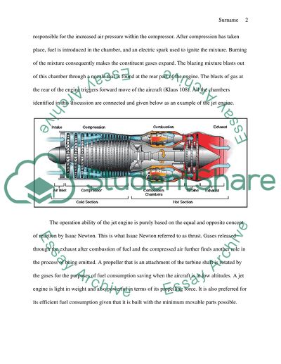
Assignment Report: The Jet Engine Jet engines are primarily used to propel airplanes forward. They make use of force produced by thrusts within the engine. This force allows a plane to fly at a very high speed. These engines are also referred to as the gas turbines. Gas turbines are a combination of all jet engines, since their functionality and operation is basically the same. The component parts of the jet engine allows for the study of its functionality based on the very specific parts that are brought together to make up the engine. This report is therefore aimed at studying this functionality by considering the contribution of each constituent part to the entire engine. Changes that have been characteristic of the jet engine will also be highlighted, owing to the dynamism of technology over time. Another thing that this report will try to assert is the suitability of the engine in its use, considering its efficiency, cost of use and operation. The consideration of the specific parts of the jet engine is the basis through which the required study can be done in order to ascertain what this report is all about. A jet engine is one interesting machine to study and compute a report on. Air is sucked into the front of the engine by a fan. From there, air’s pressure is heightened by the use of a compressor. This is achieved by the presence of blades within the compressor. The blades found in the compressor are responsible for the increased air pressure within the compressor. After compression has taken place, fuel is introduced in the chamber, and an electric spark used to ignite the mixture. Burning of the mixture consequently makes the constituent gases expand. The blazing mixture blasts out of this chamber through a nozzle that is found at the rear part of the engine. The blasts of gas at the rear of the engine triggers forward move of the aircraft (Klaus 108). All the chambers identified in this discussion are connected and given below as an example of the jet engine. The operation ability of the jet engine is purely based on the equal and opposite concept of reaction by Isaac Newton. This is what Isaac Newton referred to as thrust. Gases released through the exhaust after combustion of fuel and the compressed air further finds another role in the process of being emitted. A propeller that is an attachment of the turbine shaft is rotated by the gases for the purposes of fuel consumption saving when the aircraft is at low altitudes. A jet engine is light in weight and also powerful in terms of its propelling force. It is also preferred for its efficient fuel consumption given that it is built with the minimum movable parts possible. Axial and Centrifugal compressors are fundamental to consider in any given report that involves jet engines. Either of them can be used although they have distinctive features that make them more or less unequal and therefore the preferred property of the engine determines what compressor to use. An axial compressor is basically a rotating one like already presented in the above discussion, but an important aspect of the compressor is that the working fluid and the rotation axis move parallel to each other (Klaus 133). That is, the fluid direction of flow is parallel to the rotation axis. This is not the case in the centrifugal compressor. In the axial compressor, compressed gases flow without stopping (continuously). This compressor is associated with high capacities of mass flow, consequently becoming very effective in its functionality. Due to this outstanding feature, axial compressors are expensive compared to other type4s of compressors. On the other hand, centrifugal compressors are not so much likely to be used on aircrafts like the axial compressor. They are best suited for non-stop running processes or applications. The volume of their mass flow is relatively high, but with considerable low or no pressure. These compressors are best suited for gas turbines of small aircrafts. The effectiveness of centrifugal compressor is based n the device or machine that it is used in. for large and heavy aircrafts, the compressors are very inefficient. However, for auxiliary power suppliers and aircrafts that are considerably small, their efficiency cannot be refuted (Klaus 166). The diagrams below show axial and centrifugal compressor engines: Axial compressor Centrifugal compressor Fixed and free power turbines are crucial to consider in the analysis of Jet Engines. Outstanding differences between the two are that the free power turbine is an efficient fuel consumption aspect. Its consumption of fuel remains low while its performance is highly maintained. Another distinctive feature is the clutch power. Free power turbine does not require heavy clutch for its effective performance. On the other hand, fixed power turbine is highly responsive to changes in fuel and power, meaning that the turbines can maintain an idle mode without necessarily rotors turning (Klaus 180). In this is not the case with free power turbines. However, free power turbines are associated with torque-speed. Due to this feature, they are highly preferred in heavy vehicles over the fixed power turbines. Highest possible torque can be achieved, given a power of zero in the speed of a turbine shaft (Klaus 185). The graph below is a representation of standard torque speed curves, given a fixed or a free power turbine: Evaluating the advantages and disadvantages of power turbines in the context of free power or fixed power is important in the analysis of power demands from either of the two. The two have varied responses to power demands especially in the event that the power demand is large or sudden. The response to this demand, the effectiveness with which the responses take place and the resultant consequence of that process are just but a few aspects to put into consideration in assessing the suitability of the two in responding to power demands. High and sudden demands are best suited to the fixed power turbines. The torque speed as presented above by the diagram shows that fixed power turbines could be suitable in heavy vehicles. However, this is not the only feature that counts. The effectiveness of the turbines in performance is fundamental. In this regard, the advantages of the free power turbine surpass those of the fixed power turbine, making the free power turbine best suited to the military’s heavy vehicles. This advantage goes over and above the use on heavy vehicles to the use on helicopters, due to the suitability of the turbines in being used on flying objects. Jet engine involves a series of inward and outward movement of energy. These movements are characteristic of matter and/or energy. The entry and exit of the matter and/or energy constitutes an OPEN system that is considered in this analysis. If the opposite is considered, the analysis of the jet engine cannot be done since a jet engine is not a closed system. A jet engine consists of entry and exit of matter and/or energy in order to fully function and perform efficiently (Klaus 201). On the same note, the concept of overall efficiency can be analyzed. Overall efficiency in this report refers to the process by which a jet engine derives total heat energy from fuel, then converts this energy into a form usable by the engine and finally into a propelling energy. The ease with which the engine will do this denotes the efficiency level. Low rate of this conversion can therefore be associated with ineffectiveness, while higher rates of this conversion denote high and significant efficiency associated with the engine. The apparatus considered in the development of this report is the GT 185 Two-shaft Gas Turbine. This apparatus is an educational fully implemented and self contained suitable for use in the analysis of this report. Investigations that are possible through this apparatus are comprehensive (Klaus 212). It uses kerosene to function, allowing for the analysis of its principles as well as its performance. The apparatus is made of steel and is also fitted with a gas generator. Other parts of the two-shaft gas turbine are: power turbine, combustion chamber, oil and fuel tanks, pumps, ancillaries and guards (Klaus214). It is also instrumented and fitted with a control panel that is user friendly. The diagram below shows this apparatus: The apparatus is fitted with a turbine and a compressor, speed and load control as well as a dynamometer. All these are found at the control panel. During experimentation, any errors committed triggers warnings that are depicted by various coloring depending on the error committed. The method or procedure of carrying out an experiment using the above apparatus is suited to the abilities of students. The procedure is simple and easy to follow. It involves: Operation and functionality of the gas turbine Shaft power determination Consumption of fuel determination Turbine characteristics observation and recording Efficiency assertion of the components of the of the gas turbine, given the experiment being conducted The report is not complete without the presentation and analysis of the results that are tailored towards asserting the aim of the report. Generator results that pertain to torque and speed have to be available. Actual results here present calculations and answers that well treat the variables of the report. These variables are: heat supplied by fuel, torque, engine efficiency, mass flow rate and Carnot efficiency. The first set of results is the general observations and reading of values of fuel flow, temperatures, pressure, torque and speed, given the performance parameters of the engine. This is shown by table below: Parameter Engine speed (rpm) Load (%) Value Maximum power (kW) 2198 69.75 64.1 Maximum torque (Nm) 1280 100 399.2 Maximum thermal efficiency (g/kWh) 1574 90.1 36.45 Minimum BSFC (g/kWh) 1574 90.1 228.5 This report also provides results that denote heat supplied by fuel, engine efficiency, mass flow rate and Carnot efficiency. The results are given below: Heat supplied Mass Flow Rate Efficiency Carnot Efficiency Input values: Ambient Temperature [K] Ambient Pressure [atm] Compression Ratio [/] Cut-Off Ratio [/] Gas Constant [J/kg*K] Specific Heat [J/kg*K] Kappa [/] Input Values: Compressor Inlet Temperature [K] Compressor Inlet Pressure [atm] Turbine Inlet Temperature [K] Turbine Inlet Pressure [atm] Working Fluid Mass Flow Rate [kg/s] Fuel HHV [Btu/lbm] Specific Heat [J/kg*K] Kappa [/] Input Values: Inlet Stagnation Temperature [K] Inlet Stagnation Pressure [atm] Inlet Velocity [m/s] Conductivity [mho/m] Magnetic Field Strength [T] Loading Parameter [/] Channel Length [m] Kappa [/] Specific Heat [J/kg*K] Gas Constant [J/kg*K] Input Values: Q-Supply Temperature [K] Q-Reject Temperature [K] Calculations from the above results are given below: Heat Supplied Mass Flow Rate Efficiency Carnot Efficiency Output Values: Compression Temperature [K] Compression Pressure [atm] Combustion Temperature [K] Combustion Pressure [atm] Exhaust Temperature [K] Exhaust Pressure [atm] Cycle Efficiency [%] Heat Rate [Btu/kWhr] Output Values: Fuel Mass Flow Rate [kg/s] Thrust [N] Output Values: Inlet Static Temperature [K] Inlet Static Pressure [atm] Inlet Mach Number [/] Induced Voltage Field [V/m] Current Density [A/m^2] Outlet Stagnation Temperature [K] Outlet Stagnation Pressure [atm] Output Values: Thermal Efficiency [%] Heat Rate [Btu/kWhr] In the development of this report based on the above results, Isaac Newton’s laws of physics were of critical considerations whether theoretically or mathematically. Force is a key driving feature of the analysis presented in this report. Change in momentum is equal to the force, as the laws of physics put it. The propelling of an aircraft is equally based on this fact, as already identified. Thrust force produced by jet engine in order to propel it is an aspect of incoming air and outgoing exhaust gases. This report has further identified various factors that affect aircraft propelling through the thrust force. These are: air velocity, temperature and altitude (Klaus 229). From the above outputs derived from the input calculations that had been provided earlier. Heat supplied to the engine will depend on a number of factors as identified by its computation. The amount of air entering the engine and the amount of fuel jetted to the air will determine the amount of heat produced. The rate of combustion further dictates this factor. Efficiency of the engine is also a determinant of the heat that the engine will receive; given the fact that heat is a form of energy. It is fundamental to note that the engine speed and the load it can handle vary with efficiency of the same engine. Carnot efficiency is determined by heat rate. It is therefore important that heat supplied by the fuel be efficient. Torque produced depends on the speed of generators or turbines. Some generators do not achieve torque, but almost all turbines do. The functionality and effectiveness of an engine or a turbine is a major determinant of the torque and speed that an engine a generator or a turbine exhibits. The rate of mass flow in an engine, generator or a turbine is a factor that determines its overall efficiency. Further to the interests of this report, graphs that denote the relationship between efficiency and speed, torque and speed and power and speed are given below: Efficiency and Speed Torque and Speed Power and Speed The curves in the graphs above provide the basis through which the relationship between the above identified variables can be analyzed. This relationship is based on the interests of this report, as earlier identified in the aim of the report. In conclusion, the analysis of the jet engine is a diverse and a dynamic study. This report has identified different variables that can be deal with using different models and apparatus of analysis. The subject matter of this report is therefore reach in information and further vast opportunities to be explored in terms of research and report writing. Technological advancement has taken the center stage, with efforts tailored towards making machines as sophisticated as possible, raising their capacity of functionality and operation ability, while making them as economical as possible from time to time. Works Cited Klaus, Hunecke. Jet Engines: Fundamentals of theory, design and operation. California: Zennith Imprint, 1997 Read More
Cite this document
  • APA
  • MLA
  • CHICAGO
(“Writing assignment reports Research Paper Example | Topics and Well Written Essays - 1500 words”, n.d.)
Writing assignment reports Research Paper Example | Topics and Well Written Essays - 1500 words. Retrieved from https://studentshare.org/engineering-and-construction/1581911-writing-assignment-reports
(Writing Assignment Reports Research Paper Example | Topics and Well Written Essays - 1500 Words)
Writing Assignment Reports Research Paper Example | Topics and Well Written Essays - 1500 Words. https://studentshare.org/engineering-and-construction/1581911-writing-assignment-reports.
“Writing Assignment Reports Research Paper Example | Topics and Well Written Essays - 1500 Words”, n.d. https://studentshare.org/engineering-and-construction/1581911-writing-assignment-reports.
  • Cited: 0 times

CHECK THESE SAMPLES OF The Jet Engine Analysis

Characteristics of a Diesel Engine

Therefore, a closer look at diesel engines in locomotives will be presented in this analysis (Zhao, 2006) ... This paper ''Characteristics of a Diesel engine'' tells that Many engine manufactures have had to explore techniques to update their diesel engines and keep them within the requirements of automotive emissions regulations.... Limiting this effect decreases the power of the diesel and thus hurts the power of the engine overall....
34 Pages (8500 words) Coursework

Layout and Operation of a Jet Engine

This paper 'Layout and Operation of a jet engine" focuses on the fact that at the beginning of the 13th century, Chinese invented rockets by using the physical principle of action-reaction.... The practical application of stream turbine was widely appreciated when the practical application of the steam engine was dominating (Hunecke 2011).... Categorized as turbojet, turbofan, turboprop, or turboshaft engine, the gas turbine engines are the most significant breakthrough in the history of aviation....
9 Pages (2250 words) Case Study

Detailed Cycle Analysis of Turbofan Engine

n the analysis of the engine cycle, the bypass ratio... Turbofan is simply a gas turbine engine and a ducted fan.... Fan – The fan is at the obverse of the engine.... The fan initiates a flow of air around the engine.... The bypass air usually keeps the engine quieter, cooler and more fuel efficient.... The two whirling turbines rotate the shafts that steer both the fan and the compressors at the front part of the engine....
8 Pages (2000 words) Essay

Turbine Engine Case Through a Review of Several Components

The level of analysis provided in the academic sources reviewed ranges from introductory to deep, meaning that for learners attempting to learn about turbines the analysis will serve as an informative tool while at the same time present valuable insight to more knowledgeable persons.... In this assignment, the module outcome is checked by analyzing a turbine engine case through a review of several components of the same as documented by various scholarly....
2 Pages (500 words) Book Report/Review

Briggs & Stratton quantum engine-Interim

To do an analysis of Crankshaft, Camshaft, Piston, and Connecting Rod through Ansys software in order to comprehend the concept of stress caused during loading.... This work "Briggs & Stratton quantum engine-Interim" focuses on the finer details of the efficiency and inefficiency of the Briggs and Stratton Quantum engine.... The author outlines a workshop practical in which the engine is disassembled fully –its several parts separately put aside and detailed scrutiny of the individual parts in relation to their functions and the material it's made of....
15 Pages (3750 words) Report

Analysis on Airframe and Engine Degradation

The purpose of this paper 'analysis on Airframe and Engine Degradation' is to investigate the cause and effects of the airframe and engine degradation.... he methodology for the study combined literature review and empirical Case Study of A320 AirBus, an analysis that involved systematic sampling of aircraft to determine deviation flow of fuel due to engine degradation (DFFB) and deviation fuel flow due to apparent airframe deterioration (DFFA).... It is also recommended that the airline establishes a uniform schedule for airframe and engine maintenance to eliminate the problem of irregular degradations, and encourage airbrushing livery method to lower the rate of aircraft degradation....
14 Pages (3500 words) Research Paper

In-Flight Loss of Engine Power Eastern Airline

The paper "In-Flight Loss of engine Power Eastern Airline" describes that the view of the National Transportation Safety Board is that the occurrence of the catastrophe was due to missing O-ring seals in the detector's master chip, which led to poor lubrication and hence damage to the three engines.... When the plane was going down through 15,000 feet at about 0915:15, the oil pressure for engine number 2 lighted up.... The captain had to return to Miami to land after shutting up the affected engine....
16 Pages (4000 words) Case Study

Materials Technology: Qantas Plane Engine Failure

This case study "Materials Technology: Qantas Plane engine Failure" presents air travel that has been complicated and risky as the equipment and operations involved are prone to failure with fatal outcomes.... After stabilizing at 250knots and having attained an altitude of 7,000 ft above sea level, the crew overheard two coincident loud bangs and subsequently, the engine No2 inboards indicated some characteristics of failure.... An error message showing the 'overheat' danger sign in the engine No....
13 Pages (3250 words) Case Study
sponsored ads
We use cookies to create the best experience for you. Keep on browsing if you are OK with that, or find out how to manage cookies.
Contact Us