StudentShare
Contact Us
Sign In / Sign Up for FREE
Search
Go to advanced search...
Free

Voltage Controlled Oscillator Experiment - Research Paper Example

Cite this document
Summary
This research paper "Voltage Controlled Oscillator Experiment" discusses VCO that was designed and tested through various methods. Observations were made on how changing parameters relative to others affects VCO. Arguably, this builds on the skills acquired in class in a practical manner…
Download full paper File format: .doc, available for editing
GRAB THE BEST PAPER96.6% of users find it useful
Voltage Controlled Oscillator Experiment
Read Text Preview

Extract of sample "Voltage Controlled Oscillator Experiment"

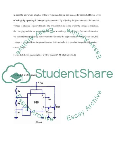
Voltage Controlled Oscillator Experiment of the al Affiliation PART 4 EXPERIMENT ON DELAY UNIT: Design and Testing The goals of this experiment are:- To investigate the characteristic of the 555 chip To develop a 555- based delay unit Create and subsequent testing of a VC O (Voltage Controlled Oscillator) Invent a trigger circuit Improve on the practical skills related to the course Background Information A circuit –controlled oscillator describes an oscillator whose frequency is fully controlled by a control voltage. The control voltage causes the frequency to rise gradually until its peak and after that fall back to its starting frequency. The harnessed input voltage controls the instant oscillation frequency. By using a control input voltage the user can tune and set with precision the pitch source hence generating frequency that are audible by human ears. It can be likened to a string of guitar whereby if it is plucked, it emanates a particular sound. Normally, all VCOs have 1V/OCT CV input. The CV alters the pitch to desired level just like a string of a guitar does when plucked with measured intensity. This is done mainly from a keyboard controller. A VCO is also termed as voltage-to-frequency converter owing to the fact its output frequency is altered to desired levels by changing the input voltage. The system comprises of a Pin 5 terminal on the voltage control that mainly functions to regulate the trigger and threshold levels of the applied signals. Normally, the control voltage equals to two-thirds of the voltage at the supply source. This can be explained by the presence voltage divider that is installed internally. In case the user wants a higher or lower regulator, the pin can manage to transmit different levels of voltage by operating it through a potentiometer. By adjusting the potentiometer, the external voltage is adjusted to desired levels. The principle behind is that when the voltage is regulated, the charging and discharging time of the capacitors changes accordingly. From the discussion, we can infer that frequency can be varied by altering the applied input voltage. To do this, the voltage is operated from the potentiometer. Alternatively, it is possible to operate it from the circuit output. Figure 1.0 shows an example of a VCO circuit (A.M Bhatt 2012 n.d) Figure 1.0: a VCO circuit One of the integral parts of the VCO is the 555 timer IC. Normally, the IC is configured first before used as an oscillator to form a stable multi-vibrator. A stable multi-vibrator comprises of two amplifying levels linked to a positive feedback loop by using two capacitive-resistance joining networks. The element that functions as an amplifier can be field-effect transistor, operational amplifier, vacuum tubes or any other form of amplifier. It has a timing circuit that oscillates from ‘high’ to ‘low’ continuously creating a train of impulses. What distinguishes a stable multi-vibrator and 555 timer IC is that the 555’s pin has an external connection to the voltage supply. With this pin, the user can control the threshold voltage. Pin two and pin six are compared by comparators that are installed internally. The output resulting from these comparators usually control the internal built flip flop circuits that buckles up 555 timer’s output and subsequently changes voltage at pin five with varying frequency at depending on the level which 555 timer’s output is toggled at. Increasing voltage at pin five reduces the output oscillation frequency and the vice-versa is also true.         EQUIPMENTS AND COMPONENTS USED: Equipment: Breadboard, Oscilloscope DC Power Supply Unit (PSU), Digital Multi-Meter (DMM), Components: Resistors (Ω): 330kΩ, 200k, 5×100k, 2×5.1k, 1k, 82, Capacitors (F): 10n, 22n 100μ (Tantalum), LEDs: LED, Chips: LMC555CN), Switch: On/Off Switch Figure 1.1: a 555 timer based VRO EXPERIMENTAL PROCEDURE 555-based oscillator was designed and built on a breadboard as shown figure 1.3 Figure 1.3: A VRO circuit Maximum and minimum values of V2 and Vout, and the durations were recorded. RA was increased to 330 kΩ and observations recorded. RA was reset to 100 kΩ and RB changed to 330kΩ and test 1 was repeated RA was set to be equal to RB=100kΩ and the supply voltage was reduced to 6V and test 1 repeated. The supply voltage was reduced to 3V and the test 1 was repeated Vcc was set to 9V and a voltage of 5V was applied to pin 5. Then V5 was changed between 0 and 8 V in steps of 1V. The minimum and maximum values of V2 and Vout together with the frequency were recorded. A graph of V2 (Maximum), V2 (Minimum), Vout (Maximum), and frequency against V5 was plotted RESULTS AND DISCUSSION DISCUSSION QUESTIONS Comparison of waveform of Vc with waveform of Vout for the NOR gate based oscillator. From the data, we can infer that the waveform for the 555 time oscillator results in a square wave. On the other hand, waveform for NOR gate based oscillator resulted to a triangular wave. During the experiment, it was also observed that when the value of RA was adjusted, the amplitudes of the waves changed proportionally in line with the adjusted value of the resistance. The output voltage also increased in a proportionate manner from 2.8 V to 10 V. Setting RA to 100 kΩ and RB to 330kΩ , it was observed that the duration for Vout=’high’ decreases from 2.98ms to 1.386ms while the Vout=’low’ period stay constant. When RA was set to be equal to RB=100kΩ and the supply voltage was reduced to 6V, then the Maximum voltage= 7 V, minimum voltage= -200mV Basing on the tests 3 and 4, we can summarize the relationship between the following values is as follows: The maximum value of V2 – Vcc is inversely proportional to V2 The maximum value of Vout - Vcc is directly proportional to Vout. The minimum value of V2 - Vcc is directly proportional to V2 GRAPHS The rationale behind changing frequency What causes the frequency to vary is that the change in voltage also leads to modification of impedance for the circuit hence changing the capacitance. Frequency is inversely proportional to the capacitance. And is related by the equation= 1/ (1.386R2*C) PART 5: PUTTING TOGETHER AND CALIBRATION The goals of this experiment are:- To interface the delay unit, oscillators and amplifier To calibrate the resultant system To improve on theoretical skills imparted in the coursework To learn the rationale behind the theory of the project Oscillators An oscillator refers to an electronic or mechanical device that functions on the principle of oscillation. Oscillation is a periodic variation between two items based on varying level of energy. All kind of oscillator operates on some basic principle whereby the oscillator uses a delicate amplifier whose output is feedback in the input phase. Hence, the signal restarts and keeps going by itself. Through this process a periodic signal, oscillating or sine waveforms or time square waveforms. The oscillator operates by converting direct current from a Alternating Current (AC) source. A classical example of oscillators include signal broadcasted from televisions and radios. COMPONENTS AND EQUIPMENT Equipment: Digital Multi-Meter (DMM), Battery: 9V with connectors, Breadboard, DC Power Supply Unit (PSU), Screwdriver Oscilloscope, Components: Resistors (O): 10k, 300k, 5×620k, Capacitors (F): 33µ, Linear Carbon, Multi-position switch Potentiometer (O): 50k Note: All resistors are of 0.25W Metal Film (: 1%) EXPERIMENTAL PROCEDURE 1. Interfacing The delay unit was connected to the oscillator as shown in the figure 2. Calibration a. The potentiometer was connected as shown in the figure b. For R3=620kΩ, the delay was adjusted to 60 sec 3. The circuit given in fig. 5.3 was built using a multi-position switch, and testing for the delay was done and recorded for each value of R3. 4. The power supply was replaced with a 9V battery, observations made. RESULTS AND DISCUSSION Delay(min) 0.5 1 2 3 4 5 R3(k) 310 620 1240 1860 2480 3100 Discussion questions Q1: If the user wants to disable the named NOR gate above, should the ‘control signal’ be ‘high’ or ‘low’? (Hint: Use the principle operations for NOR gates) Answer: the control signal should be high for disabling Q2: What is the output of the delay unit (pin 3 of 555) before the required delay is reached? Answer: Vout=9 V 4. Q1: What is the function of C5? Answer: the capacitor ensures the system never run low on power since it discharges and charges at varied intervals. 5. Q2: Why is the system applying two switches (S1 and S2)? Answer: S2 acts as a safety switch whereby it protects the components from damage resulting from excessive current flow in case they malfunction. On the other hand, S1 acts as a switch to turn on and off depending on the condition of the capacitor. CONCLUSION In the experiment, VCO was designed and tested through various methods. Observations were made on how changing parameters relative to others affects VCO. Arguably, this builds on the skills acquired in class in a practical manner. Besides, the experiment illustrated that the waveform can be different. For instance, NOR gate based oscillator gives a triangular wave while a 555 timer based gives a rectangular wave. References Anil K. Maini 2007, Digital Electronics, Principle, Devices and Application, John Wiley and Son Limited, England         Read More
Cite this document
  • APA
  • MLA
  • CHICAGO
(Voltage Controlled Oscillator Experiment Research Paper Example | Topics and Well Written Essays - 1500 words, n.d.)
Voltage Controlled Oscillator Experiment Research Paper Example | Topics and Well Written Essays - 1500 words. https://studentshare.org/design-technology/1873161-parphrase
(Voltage Controlled Oscillator Experiment Research Paper Example | Topics and Well Written Essays - 1500 Words)
Voltage Controlled Oscillator Experiment Research Paper Example | Topics and Well Written Essays - 1500 Words. https://studentshare.org/design-technology/1873161-parphrase.
“Voltage Controlled Oscillator Experiment Research Paper Example | Topics and Well Written Essays - 1500 Words”. https://studentshare.org/design-technology/1873161-parphrase.
  • Cited: 0 times

CHECK THESE SAMPLES OF Voltage Controlled Oscillator Experiment

Frequency Response of Netwroks (Electronic Engineering)

Frequency Response Networks Tutor The main objective of this experiment was to investigate how capacitive and inductive reactance's vary with frequency, plot the frequency response of a simple RC filter, plot the variation of current with frequency in a series RLC circuit and determine the resonant frequency and Q factor and to evaluate simple band- pass and band-stop filters.... hellip; The apparatus used were as follows; patch-board, farnell low frequency (LF) oscillator, oscilloscope (CD 1400 including 1 off CX1 449), digital voltmeter and digital frequency meter....
3 Pages (750 words) Lab Report

Quantitative asset managment laboratory

Aim of the experiment The primary concern of the experiment is to design and implement a Quadrature Amplitude Modulation transmitter.... The experiment aims at the student being able to understand the representation of baseband signals in constellations and to have a better knowledge of differential encoding.... The experiment also aims at reviewing the Quadrature Amplitude Modulation in digital communication, as this will help in generation of signals and demodulation....
6 Pages (1500 words) Coursework

Voltage

If the RMS voltage of the mains is 240V, find the RMS value of the current flowing in the fire and the peak values of current and voltage.... Due to a fault on the mains supply, the peak voltage surges instantaneously to 1000V.... Peak voltage would be 339.... At a peak voltage of 1000 volts, the fire would draw 17....
3 Pages (750 words) Research Paper

Cottage Cheese Experiment

The paper "Cottage Cheese experiment" describes that plate counts were used instead of direct microscopic counts or turbidity measurements because of the obvious advantages of the first method.... nbsp;… When it comes to the difference between the control cottage cheese and the experiment cottage cheese, the difference cannot be exactly determined due to insufficiency of data.... Basically we need more information on the consistency or lumpiness of the cheeses, their gross appearance after the experiment and perhaps differences in texture, temperature and other aspects....
1 Pages (250 words) Essay

Acoustic Wave and Electromechanical Resonators Concept to Key Applications

I… Finally, many thanks goes to my family as a whole for their valuable time that they offered to me during the entire project period The source of the signal that the system uses is termed as the Gunn oscillator, which is at a signal of 10.... The output power may as well be varied by varying the voltage supplied that is received by the Gunn oscillator via the unit cable attached to it (Campanella 2010)....
7 Pages (1750 words) Essay

Quantum Oscillator Problem

The quantum oscillator wave functions are given in equation 6.... The quantum oscillator wave functions are given in equation 6.... This is a quantum oscillator problem.... The quantum oscillator wave functions are given in equation 6....
1 Pages (250 words) Assignment

Light Source Voltage and the Velocity of a Solar Car

In attempts to gain insight concerning the operation of solar vehicles, an experiment is set to investigate the relationship between the light source voltage and the velocity of a solar car.... Objective of the experiment.... The objective of the experiment is to find out the effect of light source voltage on the velocity of a solar car.... The actual light source resistance remains unknown until the experiment is finalized.... In the experiment, all the other variables would be controlled in a rigid manner (Pimentel 34)....
2 Pages (500 words) Lab Report

Summary and Theory

Distinct elements in the loop in this experiment are usually separated in the industry; however, in this case, they are all put in a single small package which may make them a bit difficult to differentiate.... This assists in generating a voltage which utilized as an indicator to a controller.... The heat that is absorbed by the air is referred to as dynamic heat balance that is determined as the heat going in-the heat coming out written as The number of input voltage for an amplifier is usually assumed....
10 Pages (2500 words) Essay
sponsored ads
We use cookies to create the best experience for you. Keep on browsing if you are OK with that, or find out how to manage cookies.
Contact Us