StudentShare
Contact Us
Sign In / Sign Up for FREE
Search
Go to advanced search...
Free

Heat Exchanger Design Analysis - Coursework Example

Cite this document
Summary
The paper "Heat Exchanger Design Analysis" focuses on the critical analysis of the project in elaborating the design of a heat exchanger. This shall incorporate all the conditions at hand to have the heat within the system is within the constraints bearable for comfortable operation…
Download full paper File format: .doc, available for editing
GRAB THE BEST PAPER93.9% of users find it useful
Heat Exchanger Design Analysis
Read Text Preview

Extract of sample "Heat Exchanger Design Analysis"

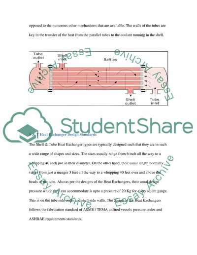
?Heat Exchanger Design Project Heat Exchanger Design Objective The objective of the project is to come up with an elaborate design of a heat exchanger. This shall incorporate all the conditions at hand so as to have the heat within the system being within the constraints that are bearable for comfortable operation. The exchange system is designed such that the composition of the coolant is 100% Freon 12. In that regard, the inlet temperature of the system is 240K. The design is also to have the outlet temperature of the 100% Freon 12 being 300 K. For the Freon, the designed pressure at the inlet is 7atm. The Flowrate of the system is to be designed to be 10,560 kg/hr The design also aims at getting the heat exchanger using hot Ethylene glycol which at the inlet shall be at a temperature of 350 K. At the outlet, the design is to have the hot ethylene at the temperature of 310K. At the same time, the design Pressure at the inlet is to be 2 atm. 2 Background Shell and Tube Heat Exchangers A shell and tube Heat Exchanger works with the principle that a series of parallel tubes run through a shell that is filled with a fluid that takes the heat from the series of parallel tubes. The tubes transfer heat into the fluid primarily through conduction and convection. It is a very effective heat exchange system where the heat is ejected from the pipes with a lot of ease. This mechanism of heat exchange is the most commonly used in industries as opposed to the numerous other mechanisms that are available. The walls of the tubes are key in the transfer of the heat from the parallel tubes to the coolant running in the shell. S & T Heat Exchanger Design Standards The Shell & Tube Heat Exchanger types are typically designed such that they are in such a wide range of shapes and sizes. The sizes usually range from 6 inch all the way to a whopping 40 inch just in their diameter. On the other hand, their usual length normally varies from just a meager 3 feet all the way to a whopping 40 feet over and above the heads of the tube. Also as per the designs of the Heat Exchangers, their usual design pressure which they can accommodate is upto a pressure of 20 Kg for every sq.cm gauge. This is on the tube side walls and shell side walls. The design of the Heat Exchangers follows the fabrication standard of ASME / TEMA unfired vessels pressure codes and ASHRAE requirements standards. The climate of the area under consideration changes seasonally and rivet holes should have a broad tolerance accordance to the four seasons of the world. It has extreme end points whose temperatures go beyond the melting point of water. Under changing environmental temperature conditions, materials tend to expand and contract. In this regard, the heat exchanger system has to be designed in way that considers the expansion and contraction of materials. The system has to be made with more flexible tolerances and fits to allow for the expansion and contraction of the materials (I). The best method for the joining of the parts of the system should be one which allows for the expansion and contraction of materials. In this regard, permanent material joining methods like welding are inappropriate. The use of rivets is recommended. The rivets should be such that they allow the joined materials room to expand and contract relative to one another. To achieve this, the rivets and the rivet holes should be designed with a great tolerance fit. The system should also be designed in a way that permits regular repairs and maintenance. It should not be rigidly enclosed. More or less all systems tend to break down at some point in the course of their work time. This calls for an entry point to check up the internal portions of the system. In this regard, it is in appropriate to design a system which is permanently enclosed within a system. Entry points can be made from several wide ranges of mechanisms. The design incorporates all the conditions at hand so as to have the heat within the system are within the constraints that are bearable for comfortable operation. The exchange system is designed such that the composition of the coolant is 100% Freon 12. In that regard, the inlet temperature of the system is 240K. The design is also to have the outlet temperature of the 100% Freon 12 being 300 K. For the Freon, the designed pressure at the inlet is 7atm. The Flowrate of the system is to be designed to be 10,560 kg/hr. The design also has the heat exchanger using hot Ethylene glycol which at the inlet shall be at a temperature of 350 K. At the outlet, the design is to have the hot ethylene at the temperature of 310K. At the same time, the design Pressure at the inlet is to be 2 atm. 3 Design methodology The shell and tube heat exchanger It has a series of tubes of which only one set of the tubes contains the flowing fluid. This fluid may be cool or heated in most cases. There is a second fluid within the shell and tube heat exchanger which runs over the tubes (being cooled or heated) so as to provide or absorb required heat. A set of tubes found within it can be referred to as the tube bundle. A shell and tube Heat Exchanger works with the principle that a series of parallel tubes run through a shell that is filled with a fluid that takes the heat from the series of parallel tubes. The tubes transfer heat into the fluid primarily through conduction and convection. It is a very effective heat exchange system where the heat is ejected from the pipes with a lot of ease. This mechanism of heat exchange is the most commonly used in industries as opposed to the numerous other mechanisms that are available. The walls of the tubes are key in the transfer of the heat from the parallel tubes to the coolant running in the shell. They may consist of plain or longitudinal tubes. It is applicable in places where temperatures greater than 260 Celsius and a pressure of more than 30 bars can be used. Such large amounts of heat can only be suited for this type of a heat exchanger because of its robust shape. Figure 1: The shell and tube heat exchanger 3.1 Overall approach The ratio of the energy output of the liquid heater to the total amount of energy delivered to the liquid heater is stated as EF (‘Energy Factor’) in equation (1.2) [4]. By means, EF is the added energy content of the liquid drawn from the heater over the energy required to heat that liquid and maintain it at a set point temperature. This equation establishes the EF for liquid heaters. ……. (1.2) *EF- Energy Factor T-Temperature (K) m- Mass of liquid drawn (kg) -Specific heat of liquid at constant pressure - Liquid heater’s daily energy consumption (kJ) As an example, a 200 watts of electricity is wasted at the heater system as shown in the table below (Table 2) to show the estimated waste in dollars, heating the liquid from 245 , for each energy factor reached by using a heat exchanger. For this example an average person's estimates, are; 180 Liters of hot liquid, 4 hours per day used to heat up the liquid, 120 days a year. Table 1-Estimated savings Per EF 3.2 Detailed Calculations and Design Justification ……. (1.2) *EF- Energy Factor T-Temperature (K) m- Mass of liquid drawn (kg) -Specific heat of liquid at constant pressure - liquid’s daily energy consumption (kJ) To calculate electric liquid poIr consumption per day: = 36 kWh used for each day over 8 hour usage Table 2-Calculated EF T-In? C T-out? C Calculated EF   Average Liters/Day of hot liquid delivery 2 45 0.591   300 5 45 0.620         10 45 0.667   at 20?C 15 45 0.715   4.183 20 45 0.762         25 45 0.810     - -kWh used for each day   30 45 0.857     36   35 45 0.905         40 45 0.952     - -kJ used for each day   45 45 1     129599   1. How much energy is generated by heat exchanger from 10 - 60 degrees of the waste liquid in (Kilo Joules)? As the warm or hot liquid goes through the drain, it clings on the surface of the drain pipe forming small films. This thin film makes it possible for high heat to transfer. The heat that was wasted is absorbed by the cold liquid flowing by the outer section; hence part of the energy used by the heating system is conserved. I can calculate the energy generated from the recovery process for example; where a heat exchanger generates energy by raising the temperature of the liquid input form 10to 60. Since this case deals with energy transfer, the formula for calculating the energy transferred is given by: *Where: Q- Energy transferred m - Mass of liquid - Specific heat of liquid dt- The temperature difference By using this equation, the specific heat of liquid is 4.19 kJ/. The liquid temperature rises from 10 to 60, so the temperature difference is 50. HoIver, the mass of liquid is not given; hence for purposes of this equation, an assumption of the liquid flow rate will be used instead, which 1.5kg/s is assuming that 1 liter is equivalent to 1 kilo. Therefore, Therefore, the heat generated is 314.25 KJ. 3.3 3.4.0 Energy Generation Damping factor Figure: Nomenclature used in the GWHE model A counter flow system enables the cold mains liquid to make a circulation in the spiral pipe as shoIr drain flows inside the drain pipe. I relied on the TRNSYS model developed by Picard (2007) for the above construction. It combines the techniques of the steady-state effectiveness in combination with a damping factor. According to the nomenclature in Figure 6; steady-state effect is equal to: The damping factor, f got introduced by Picard et al (2006). It is a representation of the transient behaviour presented by GWHE. The steady-state equation can be modified accordingly as shown below: When the GWHE is in operation (op) and standby; time constants ?opand ?sb can be equated to 30 and 300 seconds respectively. According to Picard and Bernier (2008) the performance of heat recovery receives minimal effect from the choice in the value given to ?opand ?sp. When heat recovery changes by ±5% the ?op changes by ±50% respectively. The GWHE applied in the study above has a basis on a model which is commercially available from Liquid film Energy Inc. It is the G3-60 model. The curve fitted values of the steady-state effectiveness can be obtained from the manufacturer’s data (Picard, 2007) 4 Results & Discussion – Design Iterations Discussion I chose the gravity film heat exchanger for the final project. The main reason why I chose the gravity film heat exchanger is because of its counter flow system. It is fascinating how the gravity film heat exchanger operates. Liquid flows down via the pipes, and I do not need to make any pressure. The counter flow in the gravity film heat exchanger ensures that the heating system needs minimal pressure to operate. It is fairly easy to construct within a dIlling place. The process of installation is also immensely easy. The fact that it operates its own heating with minimal pressure involved was a key motivating factor for this choice. To capture heat from liquid produced by all sources in a dwelling and put it to use would require a regenerator-type, such as a heat exchanger, one that can capture heat from liquid generated by one fixture or appliance and apply this heat to assist the hot liquid demand. The simplest system has a coil of copper pipe wrapped tightly around a section of copper drainline, since copper has high heat conductivity. Cold liquid flowing to the liquid heater flows through this coil and is preheated whenever hot liquid is going down the drain. The preheated liquid is split between the cold liquid input to the heater and the fixture, creating equal flow, which is discussed later in this report. Final Heat Exchanger Design The Shell & Tube Heat Exchanger types are typically designed such that they are in such a wide range of shapes and sizes. The sizes usually range from 6 inch all the way to a whopping 40 inch just in their diameter. On the other hand, their usual length normally varies from just a meager 3 feet all the way to a whopping 40 feet over and above the heads of the tube. Also as per the designs of the Heat Exchangers, their usual design pressure which they can accommodate is upto a pressure of 20 Kg for every sq.cm gauge. This is on the tube side walls and shell side walls. The design of the Heat Exchangers follows the fabrication standard of ASME / TEMA unfired vessels pressure codes and ASHRAE requirements standards. The design incorporates all the conditions at hand so as to have the heat within the system are within the constraints that are bearable for comfortable operation. The exchange system is designed such that the composition of the coolant is 100% Freon 12. In that regard, the inlet temperature of the system is 240K. The design is also to have the outlet temperature of the 100% Freon 12 being 300 K. For the Freon, the designed pressure at the inlet is 7atm. The Flowrate of the system is to be designed to be 10,560 kg/hr. The design also has the heat exchanger using hot Ethylene glycol which at the inlet shall be at a temperature of 350 K. At the outlet, the design is to have the hot ethylene at the temperature of 310K. At the same time, the design Pressure at the inlet is to be 2 atm. The final design incorporates a double-pipe exchanger of heat, in that regard, the thermal resistance that shall be offered by of the tube wall against the flow of heat is Bearing this in mind, the designed radius of the wall is R wall = [ln (8/7.2)] / 2*2.7*0.876*75 = 2.969*10^-4 The designed total thermal resistance is obtained from the relation; In that regard, R total = 1.759*10^-4 + 2.969*10^-4 + 0.972*10^-4 = 5.7*10^-4 The design is such that in the event that one fluid flows in the inner side of the designed circular tube, the fluid inside the shell flows in the outer side of the tube. In that regard; A i = 2.7 * 7.2 * 75 = 1458 A o = 2.7 * 8 * 75 = 1620 The rate of heat transfer into the cold fluid from the hot fluid is designed to be 2.13542 * 0.7832 = 1.6726 The rate of heat transfer from the cold into the hot fluid is designed to be 2.13542 * 0.2276 = 0.486 Assumptions made The design made some assumptions which are logical and simplified the calculation. The heat exchangers analysis is far much greatly simplify in the event that the assumptions are made. In that regard, the assumptions that follow were made. They are far much closely approximated practically: a. The flow in the exchanger is steady-flow, b. The kinetic as well as the potential changes of energy that take place in the exchanger are all negligible, c. The exchanger fluid’s specific heat is assumed to be a constant d. The axial conduction of heat that is along the tube of the exchanger is also deemed to be negligible, e. The surface that is on the outer side of the exchanger is also assumed to be perfectly insulated. f. The exchanger obeys the first law of thermodynamics which in essence requires that the transfer of the rate of heat that is ejected from fluid that is hot be precisely equal to the transfer rate of the heat into the fluid that is cold. References Kuppan, T. (2000). Heat exchanger design handbook. New York: Marcel Dekker. Nee, M. J. (2003). Heat exchanger engineering techniques: Process, air conditioning, and electronic systems : a treatise on heat exchanger installations that did not meet performance. New York: ASME Press. Shah, R. K., & Sekulic?, D. P. (2003). Fundamentals of heat exchanger design. Hoboken, NJ: John Wiley & Sons. Hewitt, G. F. (2002). HEDH: Heat exchanger design handbook 2002. New York: Begell House. Chisholm, D. (2008). Heat exchanger technology. London: Elsevier Applied Science. Read More
Tags
Cite this document
  • APA
  • MLA
  • CHICAGO
(“Heat exchanger design project Coursework Example | Topics and Well Written Essays - 2500 words”, n.d.)
Heat exchanger design project Coursework Example | Topics and Well Written Essays - 2500 words. Retrieved from https://studentshare.org/design-technology/1498899-heat-exchanger-design-project
(Heat Exchanger Design Project Coursework Example | Topics and Well Written Essays - 2500 Words)
Heat Exchanger Design Project Coursework Example | Topics and Well Written Essays - 2500 Words. https://studentshare.org/design-technology/1498899-heat-exchanger-design-project.
“Heat Exchanger Design Project Coursework Example | Topics and Well Written Essays - 2500 Words”, n.d. https://studentshare.org/design-technology/1498899-heat-exchanger-design-project.
  • Cited: 0 times

CHECK THESE SAMPLES OF Heat Exchanger Design Analysis

Test runs and pilot experiments on a carbon capture plant

hellip; The report aims to present the results from the test runs from the plant and to give an analysis of the results obtained from the experiments from the plant.... Use of principles of heat transfer, mass transfer, and gas-liquid equilibrium.... This current paper is a report on the test runs and pilot experiments on a carbon capture plant....
29 Pages (7250 words) Literature review

Heat Transfer Equipment

The design of double-pipe heat exchangers remains simplified and reserved to natural-convection heat-transfer.... The correction factor remains essential in establishing the functionality of equipment as measures compatibility of the exchanger flow.... remains unacceptable as it implies inefficiency of the chosen exchanger.... Designing of the exchanger includes consideration of the requirements of the equipment in terms of quantity of heat transferred....
20 Pages (5000 words) Essay

Difference between Originality and Plagiarism

Difference between description and analysis As Egger and Carpi point out, the term description can be defined as a detailed presentation of certain aspects, features, or characteristics of a subject matter, something experienced, seen, heard, or known; in contrast, analysis refers to the interpretation of the described information and it includes lots of lists, data, and graphs (“research methods”).... The difference between description and analysis is similar as that of data vs....
5 Pages (1250 words) Case Study

Superstructure Work Package

The Point on the local environment as well as on the potential occupants; which will make it possible to analyze the new developments in the design, operation and construction of this tall building.... The construction, design as well as the operation of The Point, representing tall building has failed in conforming to new the legislation demanding installation of understandable sustainability procedures.... Performance Standards The principal design worry for numerous tall buildings is fixed on their operational effectiveness instead of the environmental impact....
15 Pages (3750 words) Essay

Heat Transfer from Steam to Water

rdquo; The second set is described under “Corning heat exchanger.... he objective is to determine the overall heat transfer coefficient (Uo) for the external heat exchanger at two different water circulation rates.... rdquo; The main aim of this experiment is to test on the heat transfer from the steam to water and to produce analysis from the data collected in the lab.... The essay "heat Transfer from Steam to Water" describes that heat is a form of energy and the level of energy contained in a certain object is shown by the level of temperature in the object....
12 Pages (3000 words) Lab Report

Design of a Heat Exchanger Test Rig

The paper "Design of a heat exchanger Test Rig" discusses that the modelling methods illustrated, offer full dimensions where eight variables are linked by other equations.... Therefore, with the use of a heat exchanger, cooling or heating of fluids with minimal levels of energy becomes possible.... Such heat exchangers can be categorized as either direct or an indirect heat exchanger.... Further, the thermal inertia of the heat exchanger becomes negligible....
11 Pages (2750 words) Report

Design of a Heat Exchanger Test Rig

"Design of a heat exchanger Test Rig" paper analyses the basic working principle of heat exchangers focusing more on the commonly used plate heat exchanger.... It also seeks to address the means by which heat exchanger performances can be improved and enhanced.... There is a high demand for the improvement of the efficiency and effectiveness of heat exchanger models entering the market (Sundén & Brebbia 2014).... eat transfer processes also need to be enhanced and this begins by making sure the heat exchanger is in good operating condition....
12 Pages (3000 words) Coursework

Heat Exchanger Device

In the "heat exchanger Device" paper there is an explanation of the comparison of parallel flow, and cross-flow in the exchanger with a conclusion on which type of flow is the most efficient.... In the second part of this report, there is an explanation of the analysis by the logarithmic mean temperature difference, which is an equivalent mean temperature difference between two fluids for the entire heat exchanger.... The effectiveness-NTU is the other method that is used for analysis where the NTU is derived from the overall heat transfer coefficient and the maximum heat capacity of the fluids and the effectiveness is then found from NTU....
6 Pages (1500 words) Assignment
sponsored ads
We use cookies to create the best experience for you. Keep on browsing if you are OK with that, or find out how to manage cookies.
Contact Us