StudentShare

Our website is a unique platform where students can share their papers in a matter of giving an example of the work to be done. If you find papers
matching your topic, you may use them only as an example of work. This is 100% legal. You may not submit downloaded papers as your own, that is cheating. Also you
should remember, that this work was alredy submitted once by a student who originally wrote it.
✕
Free
The Electric Motors - Report Example
Summary
This paper 'The Electric Motors' tells that Electric motor is a device that converts electric energy into mechanical energy. All the electric motors work on a shared principle, i.e., a torque is produced on a current-carrying loop; when placed in a magnetic field, this torque makes rotation in the …
- Subject: Engineering and Construction
- Type: Report
- Level: Ph.D.
- Pages: 4 (1000 words)
- Downloads: 0
- Author: fpacocha
Extract of sample "The Electric Motors"
Q1. (a) Electric motor is a device which converts electric energy into mechanical energy. All the electrical motors work on a common principle i.e. atorque is produced on a current carrying loop; when it is placed in a magnetic field and this torque produces rotation in the loop as schematically shown in Fig. 1 [1]. This torque is then used to drive external loads by means of suitable drive mechanism.
Fig. 1: Schematic Drawing Showing Working of an Electric Motor [1]
Three different types of electric motors and their operating principle are briefly described below.
(i) DC Motor: This motor uses a DC current. An armature is placed between magnetic poles, known as field poles. Field poles remain stationary and provide the static magnetic field which runs from North Pole to South Pole. The armature is mounted on bearing and there is winding of conduction wire on it. When a DC current is made to pass through the windings on the armature, it becomes an electromagnet and the interaction between the pole magnet and the armature electromagnet forces the armature to turn until North and South poles of the two magnets align. Once this happens direction of the current in the armature windings is reversed to switch the North and South poles using a Commutator and thus the armature keeps on rotating [2].
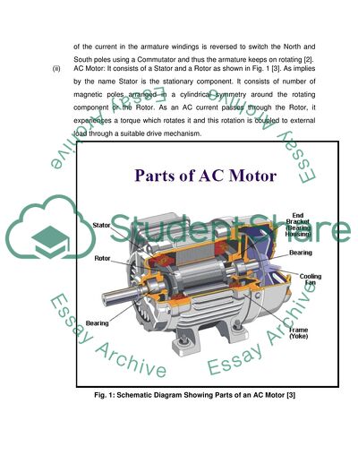
(ii) AC Motor: It consists of a Stator and a Rotor as shown in Fig. 1 [3]. As implies by the name Stator is the stationary component. It consists of number of magnetic poles arranged in a cylindrical symmetry around the rotating component or the Rotor. As an AC current passes through the Rotor, it experiences a torque which rotates it and this rotation is coupled to external load through a suitable drive mechanism.
Fig. 1: Schematic Diagram Showing Parts of an AC Motor [3]
(iii) Servo Motor: It is primarily a DC motor, but is much more refined one. It consists of a sensor to sense position of the shaft and used this as feedback to control speed of the DC motor [4].
Q1. (b) (i) Applications of Motors
DC motor: It is much easier to control speed in case of DC motors and therefore, these motors are preferred for applications where speed control is very important. Computer disc drive is one very important application of DC motor.
AC motor: It is inexpensive; however, the speed control is not good. One typical application of an AC motor is to drive fans where speed control is not so critical.
Servo Motor: It is feedback controlled system and hence it is used for applications which need precise position and speed control. One such application is drive for CNC stage, where control of position and speed is very critical.
Q1. (b) (ii) Speed Control
DC Motor:
In a DC motor the back electromagnetic force and torque is given by the following equations.
Back electromagnetic force: E = KΦN
Torque: T = KΦIa
Where:
E = electromagnetic force developed at armature terminal (volt)
Φ = field flux which is directly proportional to field current
N = speed in RPM (revolutions per minute)
T = electromagnetic torque
Ia = armature current
K = an equation constan
Therefore, speed of DC motors can be controlled by controlling either armature voltage or field current.
AC Motor: Control of speed is difficult for AC motors. Speed of a synchronous AC motor is given by the following equation [5].
Ns = 120 f / P
Where:
f = frequency of the supply frequency
P= number of poles
It can however, be controlled by using variable frequency drive, because speed of an AC motor can be controlled by controlling frequency of AC supply only.
Servo Motor: It is a DC motor only so speed can be controlled in the same manner as in case of a DC motor. It uses a feedback system to control its speed.
Q1. (b) (iii) Two Limitations
DC Motor: Power is limited due to difficulty in commutation at high size. This limits application of DC motors for high power applications. Besides, there can be sparks from the commutator especially at higher powers. Therefore, a DC motor cannot be used in hazardous and fire prone areas.
AC Motor: Speed control is more difficult. Cannot be used in applications where speed and position control is critical. If one goes for speed control then one need to add variable frequency drive, which decreases the quality of the power supply.
Servo Motor: It is expensive because it uses feedback system for real time regulation of motor speed. Besides, it has all the limitations of a DC motor.
Q2. Accuracy of Instrumentation System
An instrumentation system is attached to engineering systems for monitoring many useful parameters like speed, position, temperature, etc. This required for process monitoring, process control in real time and many times for quality control applications. However, accuracy of the instrumentation system is influenced by many factors like scale errors, offset errors, temperature, component tolerances etc. which is briefly discussed below.
(a) Scale Errors:
Scale error or least count error arises from the minimum division on a scale [6]. For example let us consider a meter scale, which is divided into 1000 equal parts and therefore the least count of this scale is 1 mm. If we measure length of an object using this scale, then we can make definite measurement only up to millimeter and any further measurement below that will be essentially an estimate only and will have errors in it. This error is termed as Scale error. Any instrumentation systems make many such direct measurements using a scale and therefore, all these measurements have a scale error built into it. The final value that we read from an instrumentation system is usually arrived at by combining many such direct measurements like value of speed is derived by measuring change in position i.e. displacement and time and then dividing displacement with time. As the measurement of displacement and time both will have scale errors and therefore, these errors will combine to give error in the value of displacement.
(b) Offset Errors:
This is also known as zero error [7]. If zero error is known, then one can get rid of it by suitable addition or subtraction of suitable value. However, in an instrumentation system there are many measurements and one or more of it can have offset error, which is not known; then offset error gets included in the final output. Besides, the offset error also crop up during service of the system due to temperature, component tolerance etc. and this may contribute to the total error in the measurement.
(c) Temperature:
Temperature affects basic attributes or properties of the instrumentation system, which is many times difficult to account for. Many measurements are made using transducers which converts the displacement into electrical current, which is transmitted through a wire to measuring system in the instrumentation system. Change in temperature may change resistivity of this wire itself and this will lead to erroneous measurement.
(d) Component Tolerances:
Component tolerances cause backlash in case of moving parts in a system and this incorporates many errors like offset or zero error. This contributes to overall error of the instrumentation system.
References:
[1] C.R. Nave, Department of Physics and Astronomy, Georgia State University. How does an electric motor work? In: Hyperphysics, Electricity and Magnetism. 2005
http://hyperphysics.phy-astr.gsu.edu/hbase/hframe.html
[2] Bureau of Energy Efficiency (BEE), Ministry of Power, India. Components of an Electric Motor. 2005
[3] etidweb.tamu.edu/.../Chapter%2013%20–%20AC%20Motors.ppt
[4] Patrick, Dale R; Fardo, Stephen W., Rotating Electrical Machines and Power Systems (2nd Edition)1997 Fairmont Press, Inc. ISBN 978-0-88173-239-9 chapter 11
[5] Parekh, R., Microchip Technology Inc. AC Induction Motors Fundamentals, AN887. 2003. www.microchip.com, ww1.microchip.com/downloads/en/AppNotes/00887a.pdf
[6] http://www.excellup.com/Notes/11_Physics_Units&Measurement.pdf
[7] http://www.springerlink.com/content/4728g713483v8785
Read
More
sponsored ads
Save Your Time for More Important Things
Let us write or edit the report on your topic
"The Electric Motors"
with a personal 20% discount.
GRAB THE BEST PAPER
