StudentShare

Our website is a unique platform where students can share their papers in a matter of giving an example of the work to be done. If you find papers
matching your topic, you may use them only as an example of work. This is 100% legal. You may not submit downloaded papers as your own, that is cheating. Also you
should remember, that this work was alredy submitted once by a student who originally wrote it.
✕
Free
The Finite Element Method - Math Problem Example
Summary
The paper "The Finite Element Method" tells us about numerical procedure used for finding approximate solutions of partial differential equations (PDE). Problems which use this method are usually too complicated to be solved by classical analytical methods and require significant computational solving capabilities…
- Subject: Engineering and Construction
- Type: Math Problem
- Level: Masters
- Pages: 4 (1000 words)
- Downloads: 1
- Author: emanuel31
Extract of sample "The Finite Element Method"
1.0 The Finite Element Method―Background The finite element method (FEM) is a numerical procedure used for finding approximate solutions of partial differential equations (PDE). Problems which use this method are usually too complicated to be solved by classical analytical methods and require significant computational solving capabilities. The solution approach is based either on eliminating the differential equation completely (steady state problems), or translating the partial differential equations into equivalent ordinary differential equations, which are then solved using standard techniques such as finite differences.
One of the main challenges in solving partial differential equations is to use equations which are approximate but numerically stable so that error accumulation does not cause the solution to be meaningless. The finite element method is an excellent technique for solving partial differential equations over complex domains. Application of the finite element method in structural mechanics is based on an energy principle, such as the virtual work principle, which provides a general, intuitive and physical basis.
The finite element method originated as a technique used to solve stress analysis problems, but today it can be applied to a multitude of disciplines ranging from fluid mechanics, to heat transfer to electromagnetism.
2.0 Problem Statement
The buckle of a standard lap belt used in passenger aircrafts has been designed and is ready to undergo testing. In order to be released into the market, the strap system must be able to withstand a 450 kg tensile load. It is assumed that the weakest point of the design is the flat plate of the buckle. Thus, prior to engaging in a costly test scenario, a simple finite element analysis of the buckle is to be made to insure soundness of design, i.e. the material does not exceed its yield strength and no significant distortion occurs. Preparing the problem for analysis first requires definition of assumptions.
2.1 Part Geometry
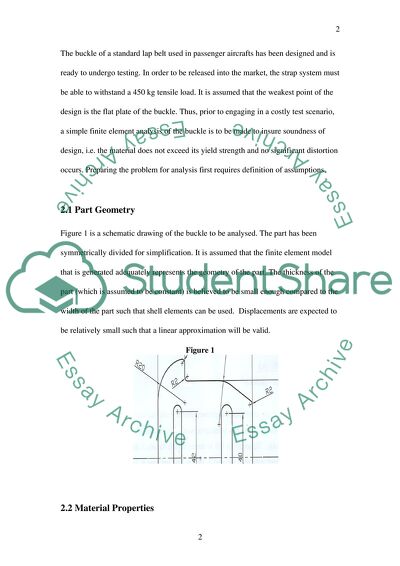
Figure 1 is a schematic drawing of the buckle to be analysed. The part has been symmetrically divided for simplification. It is assumed that the finite element model that is generated adequately represents the geometry of the part. The thickness of the part (which is assumed to be constant) is believed to be small enough compared to the width of the part such that shell elements can be used. Displacements are expected to be relatively small such that a linear approximation will be valid.
Figure 1
2.2 Material Properties
The part is manufactured from 2.5 mm stainless steel plate with a Youngs modulus of elasticity of 206 GN/m2, Poisons ratio of 0.3, and a yield strength of 580 MN/m2. Homogeneous and isotropic material was assumed with no discontinuities or residual stresses present as a result of manufacturing processes such as forging, rolling and welding. The material is assumed to have linear elastic properties.
2.3 Mesh
A mesh that provides a good representation of the model is critical for an accurate solution; the elements must be well-shaped and close fit. For this analysis, the element type chosen was PLANE82, which is a 2D structural solid element. The element has 8 nodes, which increases calculation time over its 4-node counterpart but also increase accuracy of solution. Eight-noded elements are also known to be more accurate for modelling curved boundaries, which is where the areas of maximum stress were expected in the buckle. The PLANE 82 element type also offered the benefit of accounting for a thickness value in its input properties. Since maximum stress values were expected in the curved sections of the part, two meshing values were utilised, thus providing a denser mesh in critical areas. In the curved areas, a value of 0.25 was used, while 0.51 was used in the rest of the model.
2.4 Boundary Conditions
Determination and application of boundary conditions is critical to the analysis. For this model, it was assumed that displacements would be small enough so as to not affect loading, friction losses would be negligible, and interfaces are considered to be rigid and unaffected by displacement. The tensile load is 450 kg applied uniformly across well-defined areas.
The part is constrained to resist rotation. In Figure 2, the centre of mass can be seen placed at a location 37.5 mm from the short edge or 32.5 from the long edge.
Figure 2
The force applied to the model must be determined. This is calculated by distributing the load across an area where it would be applied in an actual situation. Thus, the force is the tensile load multiplied by acceleration we have:
Force = 450 kg X 9.81m/s2 = 4414.5 N
Since the two slots in the parts have different areas, the load distribution will be different (see Figure 3 for definition of parts A and B). On part A, area can be calculated as:
Total Area Part A= 42 mm X 2.5 mm= 105 mm2
Then the load on part A can be determined as:
Pressure load = Force / Total Area = 4414.5 /105 = 42.042 N/mm2
Similarly for part B:
Force = 450 kg X 9.81m/s2 = 4414.5 N
Total Area Part B= 40 mm X 2.5 mm= 100 mm2
Pressure load = Force / Total Area = 4414.5 /100 = 44.145 N/mm2
Figure 3
Part A Part B
3.0 Analysis
The ANSYS interface of Figure 4 is a snapshot of the Main Menu and Status bar to provide an overview of how data is placed into the software.
Figure 4
Once the model is meshed, and the material properties and boundary conditions are placed, the solution phase can be run. Figure 5 depicts the meshed model with applied loads.
Figure 5
4.0 Results
The solution depicting
Von Mises stresses across the entire model are shown in Figure 6. As was expected, the maximum stresses occurred in the curved regions. Figure 7 displays the results of part A and shows that the maximum stress in the buckle was around the curve in and reached a value of 661.058 N/mm2 which exceeds the yield strength (580 MN/m2) of the stainless steel material used for the buckle. Figure 8 depicts the results of the finite element analysis for part B, which essentially mimic the results of part A.
Figure 6
Figure 7
Figure 8
A maximum displacement of nearly 8 mm occurring due to the applied force can be seen in Figure 9. This value can also be directly used to calculate the strain in the material, and with the elastic modulus and generalized Hookes Law, it should confirm the FEA prediction.
Figure 9
5.0 Conclusions and Recommendation
The finite element analysis predicted that a 450 kg force applied across the modelled buckle would cause the material to attain concentrated stresses of 661 N/mm2. This stress level would exceed the 580 N/mm2 yield strength of the material; and thus, according to the problem statement, the component would not be deemed suitable for sale. The significant distortion is also an indication that the design is not sound.
Although the method of finite element analysis is an approximate numerical estimate and exact results can only be determined through applied tests, the calculated stresses are 14% higher than the yield strength, which is not an insignificant amount.
Thus, my recommendation is that redesign should occur followed by another finite element analysis prior to testing.
References
Cook, R. D., Malkus, D. S. & Plesha, M. E. (1989). Concepts and applications of finite element analysis. New York: John Wiley & Sons.
Craig, R. R. Jr., (1996). Mechanics of materials (1st ed.). New York: Wiley.
Fagan, M. J. (1992) Finite element analysis theory and practice. Singapore: Longman Singapore Publishers (Pte) Ltd.
Taylor, R L., & Zienkiewicz, O. C. (2000). The finite element method (5th ed.) volume1: The basis. Oxford: Butterworth Heinemann.
efunda (2007) Material properties stainless steel AISI type 302. Retrieved from: http://www.efunda.com/materials/alloys/stainless_steels/show_stainless.cf m?ID=A ISI_Type_302&prop=all&Page_Title=AISI%20Type%20302.
Read
More
sponsored ads
Save Your Time for More Important Things
Let us write or edit the math problem on your topic
"The Finite Element Method"
with a personal 20% discount.
GRAB THE BEST PAPER
